Author: Paul Stafford
TechBeat Tuesday – AutoCAD Tip #7: How to Use Trim and Extend Even Faster
I’ll show you some simple workflows that I use to save time and make AutoCAD work even more efficiently. Trim and Extend are two important commands that I use – A LOT. These tips for making those commands work even faster can save you a little bit of time that will add up to a lot of time saving in the long term.
METHOD 1
Start the trim tr; or extend ex command – press enter twice
…now everything is a cutting or boundary edge
METHOD 2
Use the fillet f command, select first line then shift select second line to extend and join lines in one step. Thanks to Beekee for alerting me to this little gem.
QUESTIONS?
I hope you found this helpful. Let me know if you use this method too! Click on the CADsmarter logo below to email me
Paul Stafford
TechBeat Tuesday – AutoCAD Tip #6: How to Remove XREF Layers from the Layer List
WHY REMOVE XREF LAYERS FROM THE LAYER LIST?
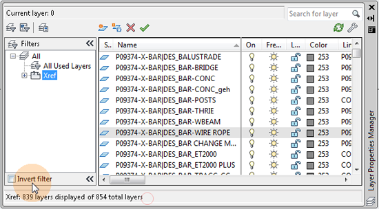
Every consultants drawing that you xref into your drawing has layers that show up in your Layer Manager. This quickly adds up to lots of xref layers to navigate through to find what you need. You don’t want to be scrolling through hundreds of xref layers searching for a particular layer. This takes valuable time – and time is money – particularly in a small business. So what is a smarter way to use the Layer Manager?
WATCH THE VIDEO TO SEE HOW TO REMOVE THE CONSULTANT XREF LAYERS
KEY INFORMATION ABOUT THE PROPERTY FILTER FOR YOUR XREF LAYERS
NOTE: at 1:10 in the video the four (4) characters to enter for the property filter are shown in the image below:
MY PREFERRED METHOD AND WHY
I prefer the second method of creating a property filter for the following reasons:
- Your new property filter is available for use all the time through the life of the project
- The small time investment needed is well worth the long term time saving benefit every single time you use the filter
- It’s quicker – less clicking – than using the invert filter method
ANY QUESTIONS?
That’s all for this tip. Which of these methods do you use? Or do you have another method? I’d love to hear about it. Click on the CADsmarter logo below to email me…
Paul Stafford
Tech Beat Tuesday – AutoCAD Tip #1: Paving Header Course
If boosting work efficiency is one of your New Year’s resolutions, you’ll love Land8’s new series. To kick off the new year, Land8 member Paul Stafford will be contributing his AutoCAD tips and tricks every week as part of Tech Beat Tuesdays. Keep reading for his easy to follow tutorial on creating paving header course!
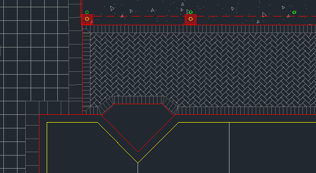
A paving header course adds an extra level of detail to your hard finishes plans and graphically helps to complete the picture. If used together with a paving hatch pattern it gives a very good indication of your design intent. But the paving header course can be very time consuming to create if you do it all manually. The paver size I will represent is 230mm long x 115mm wide x 60mm thick – though of course for this purpose the thickness is irrelevant.
WATCH THE VIDEO BELOW TO SEE HOW TO DO IT
STEP BY STEP INSTRUCTIONS
ANY QUESTIONS?
Did you find that helpful? I will do another post that shows how to handle the paving corners. Let me know if you have any comments/questions/suggestions.
Paul Stafford
AutoCAD Tip #4: Boost Your AutoCAD Productivity with an AutoLISP Program File
AutoLISP is a programming language that works with the full version of AutoCAD. Though it doesn’t work natively with AutoCAD LT, there are 3rd party addons that do enable AutoLISP for AutoCAD LT. At it’s most simple level, AutoLISP can be used to automate repetitive tasks to help increase your AutoCAD productivity. For example an AutoLISP program that I use all the time can calculate the total area of all polylines on each layer in the drawing – HUGE time saver. At the other end of the spectrum AutoLISP can create hugely complex programs that can vastly increase the functionality of AutoCAD.
WATCH THE VIDEO TO SEE TWO WAYS TO LOAD AN AUTOLISP PROGRAM FILE
METHOD 1
Drag the AutoLISP file onto your AutoCAD drawing. This is very quick method. The downside is that the AutoLISP is only loaded into the current drawing session and is not retained when the drawing is closed. Hence will need to be re-loaded every time the drawing is opened.
METHOD 2
Using the appload command and loading the AutoLISP file into the startup suite. Then every time you open a new drawing the particular AutoLISP file will automatically be loaded.
METHOD 3
This method is aimed at advanced users and CAD managers. I won’t go into any detail but just mention it so you’re aware of it. You can amend the acaddoc.lsp file to load the particular AutoLISP file automatically whenever you open a new drawing.
ANY QUESTIONS?
I’m happy to admit that I’m a bit of a novice with LISP. I know the basics and can create some simple programs to improve my productivity. If you want to know more there’s lots of resources online. Try AfraLISP and Lee Mac for starters.
Paul Stafford
TechBeat Tuesday – AutoCAD Tip #5: Quantity Takeoff and Costing Spreadsheet
A common requirement in a design business is the need to do a quantity takeoff and costing spreadsheet for your design at each phase of the project. The following describes a fairly basic process to achieve this using AutoCAD and either Excel, OpenOffice or Google Apps.
The quantity takeoff and costing spreadsheet creation method I will demonstrate requires the following:
1. AUTOCAD DRAWING
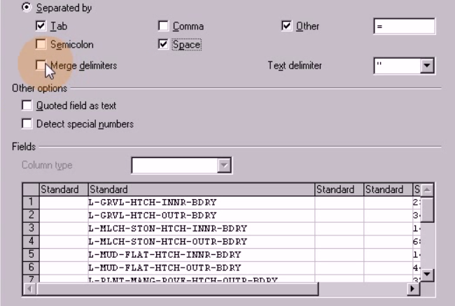
An AutoCAD drawing with a hatch boundary polyline on a unique layer for each and every different treatment type. Thus each and every treatment has a unique hatch layer and hatch boundary layer. For example the concrete pavement layer names would be
L-PAVE-CONC-HTCH – this is the hatch layer
L-PAVE-CONC-HTCH-BDRY – this is the hatch boundary layer
Good layer naming and management is vital to any AutoCAD drawing so this should not be a big task to set-up. This allows for an easy area calculation for all treatments which is part of the quantity takeoff.
2. AUTOCAD DRAWING
An AutoCAD drawing with a uniquely named block for each and every tree species and feature shrub. For example my name for the tree block for each Agonis flexuosa tree would be AGF. This allows for an easy count of the trees which is part of the quantity takeoff.
3. LISP CODE
What is LISP? It is short for AutoLISP and is a programming language specifically for AutoCAD (but not AutoCAd LT). If you want to read more see here. Get the required LISP code from the last post – #7 here. This is the routine that does the treatment area calculation for the quantity takeoff. Copy and paste it into Notepad. Save the file as SAL_SumAreaLayer.lsp
NOTE: this lisp routine was kindly posted on the CADTutor forum by Vladimir Azarko – it is not my creation nor am I claiming it to be.
YOU NEED TO DO STEP 4a OR 4b…
4a. BCOUNT TOOL FROM EXPRESS TOOLS
Express tools is a suite of tools to help expand the AutoCAD tool set. If you haven’t loaded express tools here is how you do it for AutoCAD 2013
4b. LISP FILE
Download the LISP file from here. This is the routine that counts the tree blocks as part of the quantity takeoff.
NOTE: this lisp routine was created by Lee Mac – it is not my creation nor am I claiming it to be. Have a good look around Lee Mac’s website – he’s the master of lisp.
5. EXCEL, OPENOFFICE OR GOOGLE APPS TEMPLATE FILE
I’ll be using an OpenOffice template file with the formulas set-up to use the quantity takeoff data and make the calculations to create the costing spreadsheet. It will also work perfectly with an Excel or Google Apps Spreadsheet.
VIDEO SHOWING HOW TO DO IT
See the video below for the step-by-step instructions for how to do the quantity takeoff and costing spreadsheet. The costs that I have used in the spreadsheet are not true – I have used them only to show how the formulas work:
WHY IS THIS A GOOD METHOD?
The great thing about this method for quantity takeoff and costing spreadsheet creation is that you can use it through the whole project and update it as the design is amended. That way you will always have an accurate costing for your design. There are other more automated ways to achieve this end result and I may look at them in a future post.
ANY QUESTIONS?
Thanks for reading and apologies for the long post. Let me know if you found this information useful. Let me know how you do your quantity takeoff and costing spreadsheet. Also if you have any questions or suggestions then please go to the comments section just below here and start typing…I’m waiting for your questions….
Paul Stafford
TechBeat Tuesday – AutoCAD Tip #2: Set the Correct Hatch Scale
In this week’s quick AutoCAD tip I will show you how to set the correct hatch scale to get it to show at the size you need.
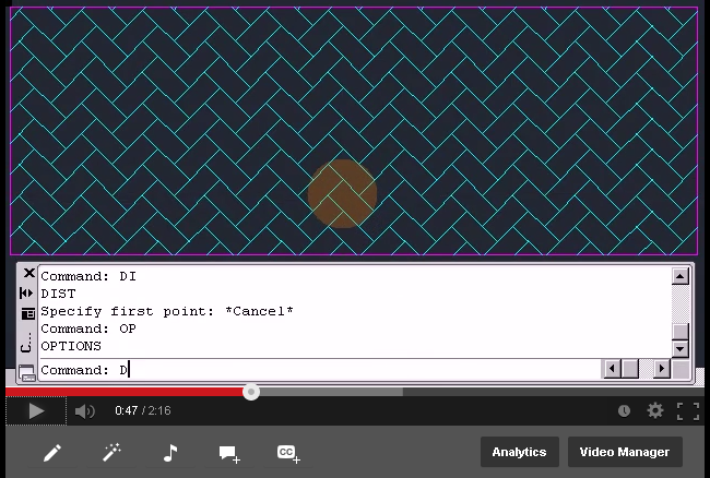
In the process of creating your hard finishes documentation you might decide that you want to represent the unit pavers with the correct hatch scale for the actual unit paver size. The reason for this might be to help you work out where the cuts are, how it works in with the headers, door openings and other structures.
In this case I will be representing a 220 x 110 mm unit paver and will use the hatch pattern AR-HBONE.
WATCH THE VIDEO TO SEE HOW TO DO IT
Is the video not working? Try this link.
ANY QUESTIONS?
Did you find that helpful? Let me know if you have any comments/questions/suggestions.
Paul Stafford
If you’ve missed any, you can also check out the rest of my AutoCAD tips on Land8.
TechBeat Tuesday – AutoCAD Tip #3: Two Reasons NOT to Use the Defpoints Layer
Though it might be tempting, drawing on the defpoints layer might not be the best idea. Since the layer doesn’t plot, many designers like to use the defpoints layer to add construction lines, notes to other team members, and other information. In this post, I’ll explain why the downsides of using a defpoint layer can outweigh its advantages.
WHAT IS THE DEFPOINTS LAYER?
The defpoints layer is created automatically by AutoCAD when you create dimensions and contains the definition points of these dimensions. I’m not sure exactly what these definition points are but I know from experience that drawing on the defpoints layer can be bad news.
WHAT IS THE PROBLEM WITH DRAWING ON THE DEFPOINTS LAYER?
There are two main reasons why using the defpoints layer is a bad idea:
PROBLEM 1.
If layer zero gets frozen then everything that is on the defpoints layer is unable to be selected. This might not seem like much but if you’re not aware of it you can waste lots of time trying to work out why you can’t select anything on the defpoints layer. Not to mention if you are working in a team and someone else will be using your drawing it can be even more confusing for them.
PROBLEM 2.
If you run the AUDIT command this will create a new layer called $AUDIT-BAD-LAYER and put everything that was on the defpoints layer onto this new layer. The previously non-plotting objects will now plot as they are not on a no-plot layer anymore – see this link for more information.
SO…WHAT IS THE BEST WAY TO HANDLE THIS?
The best practise is to create your own no plot layer, or series of no plot layers, and this will ensure that you don’t have to worry about this happening. It will also make your other team members happy.
ANY QUESTIONS?
That’s all for this tip. How does your office treat the defpoints layer? Leave a comment below and let us know how your office treats the defpoints layer.
Paul Stafford
Also appeared on CADsmarter
If you’ve missed any, you can also check out the rest of my AutoCAD tips on Land8.


