


12 search results for "urbanlisp"
If you didn't find what you were looking for try searching again.

There are Over 100 Awesome and FREE AutoCAD Commands Waiting for you
UrbanLISP is celebrating; in 2016 the app store exceeded 100 AutoCAD commands. As a holiday offer all commands are now available FREE as social download! Of the many programs we use in landscape architecture AutoCAD is an essential one. For years now I develop AutoCAD commands, like the ones in the video above, inspired on projects in urban design and landscape architecture by renowned offices. In my UrbanLISP app store you can find the more extensive ones. This year I managed to release a whopping amount of 16 new commands. WATCH >>> UrbanLISP promo
Through that there are now over 100 commands available for you to download. A number that is reason for celebration. How do we celebrate? By offering all commands for free! Temporarily you can download ALL commands as a social download. Tweet or post the command on Facebook and you can download it for free and try it out for a while. 100 commands with a video to show what the command does. There’s about 4 hours worth of video material you can watch. That is a lot! So where to start? In order to get you going I give you my personal top 5 of AutoCAD commands from the UrbanLISP app store and I will tell you why it’s one of my favourites.
5. Hatch Random
WATCH >>> Hatch Random
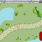
Download here Hatch Random is one of the first commands I’ve written and from my favourite category of commands; the randomisers. I was working a lot on urban plans for new residential areas, like this one in Amersfoort, the Netherlands, organising the plots and houses. The idea behind these plans was that every house should be different or at least be read as The idea behind these plans was that every house should be different or at least be read as individual house like you would see for instance in the historic centre of Amsterdam. A house is a place where a person or family lives, it’s part of your identity. As nobody is the same nor should the house be. A garden is an even stronger expression of personal identity. Like people, few gardens are exactly the same. This is something you can express easily in a plan drawing. By applying the colour green in a variety of shades randomly to the gardens you get a very expressive drawing.
4. Categorize
WATCH >>> Categorize
Download here One of the main tasks in the development of the plans mentioned above was the organisation of the plots. The masterplans I’ve worked on often contained no less than 500 plots. The plots are the saleable parts of the plan so the clients always want to know how big these plots are. Although it is possible to write the area of a polyline in it, with 500 to a 1000 plots the amount of numbers dance in front of your eyes. With Categorize however you can hatch the plots on a layer according to its size. As a result you get a very graphic representation of the size of the plots in your plans. All of a sudden calculations become fun!
3. Dimension Level Polyline
WATCH >>> Dimension Level of Polyline
Download here Besides plan drawings it is very common to make sections in landscape architecture to see the spatial ratios of your plan. They are also useful to understand the levels in your plan. This dimensioning tool combines very basic AutoCAD features into a powerful command for landscape architecture. The command uses a basic AutoCAD line entity as a reference for the level in your section. After all a level is a flat surface so a line is a perfect way to represent a level. In every section you can make a contour of the space. When you create a polyline to emphasise the contour you have a second basic AutoCAD entity. By applying ‘Dimension Level Polyline’ the command places a multileader, the third basic AutoCAD entity, pointing to every vertex of the polyline. The multileader shows the distance between that vertex and the line representing the level. So in one action you add all relevant levels to your section.
2. Measure Alternating
WATCH >>> Measure Alternating
Download here In the masterplans I’ve made the main roads are often guided by rows of trees in order to create beautiful lanes. It is common practise to draw a tree as a block. Measure and divide are two native AutoCAD commands that place trees on linear entities such as lines, arcs and polylines. I took these principals to make many similar commands with a lot more options. After all, in landscape architecture you should be able to place a tree on the exact position you want it to be without too much hassle. ‘Measure Alternating’ is such a command. What I like so much about this command is the composition of the trees in the end is of mathematic perfection based on one single linear entity. Creating a row of alternating trees along a line is not that hard. Creating it along an arc is a bit harder but still doable. Creating it along a polyline with a lot of curves, something that occurred a lot in the masterplans I’ve made, is extremely time consuming and hardly ever done right. ‘Measure Alternating’ is an easy way to do this. Besides it being quick the mathematic perfection makes the plan drawing easier to read. Be sure to make the polyline segments tangent to one an other, as I described in a previous article.
1. Grass In Elevation
WATCH >>> Grass in Elevation
Download here Although I am a big fan of blocks I am reluctant to use them when it comes to nature in sections and elevations. You can use blocks for grass for instance. When you do however you will always read a repetition of that block. Grass in reality never shows any repetition. Besides, the stretches of grass you need to draw are hardly every exactly the length of that block. That means you have to cut or scale the block somewhere, somehow. Not to mention let the block follow curving landscapes. ‘Grass In Elevation’ allows you to pick a linear entity and draws grass on it. It does it randomly so the grass doesn’t show repetition and it does it on the exact length of the linear entity so you don’t need to remove anything. It is one of the essential commands in my work. Through this top 5 I try to show a glimpse of the many ways work in AutoCAD can be optimised. There are so many ways! Whether it is for conceptual designing or engineering. Whatever you use it for, you’ll find out drawing in AutoCAD becomes a lot more fun. Browse through the app store or have a look at the previous articles I’ve written for LAN. Follow UrbanLISP on Twitter or Facebook and receive tips a few times a week. Enjoy!
Article by Rob Koningen. Recommended Reading:
- Digital Drawing for Landscape Architecture by Bradley Cantrell
- Detail in Contemporary Landscape Architecture by Virginia McLeod
Preparing Your AutoCAD File for SketchUp: The Essential Guide
An AutoCAD tutorial on how to prepare your AutoCAD file for SketchUp in just a few seconds from our resident AutoCAD expert UrbanLISP. As Kevin J. Pfeiffer has explained previously, AutoCAD drawings of your projects are good bases to build 3d models in SketchUp. Every CAD program has its benefits but sure enough also its downsides. In addition to Kevin’s article “How to Make Quick 3D Models From AutoCAD to SketchUp”, let’s have a closer look at those downsides and more importantly how to prepare your AutoCAD drawing for SketchUp.
Linear Entities
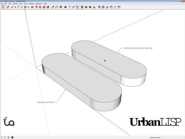
The drawing Kevin imported in his article is a simple plaza design made up only of linear entities. If that’s the level of drawing you want to import you might want to consider setting it up in SketchUp from the start. It’s more likely, however, that your AutoCAD drawing is developed a bit further. But let’s start with a drawing with only linear entities like Kevin’s. In the image below you see a screen shot of SketchUp. There are two similar shapes, both created in AutoCAD. The lower shape is a closed polyline. The upper shape consists of two arcs and two lines; the polyline after exploding it. See these AutoCAD tutorials:
- 4 AutoCAD Commands to Draw Paving Patterns on Curving Paths
- How to Show Topography in your Plan Drawing in AutoCAD
- How to Place Large Quantities of Trees in a Master Plan Instantly with AutoCAD
Let’s assume we have SketchUp Pro available, as only the Pro version will import files from AutoCAD. Since going out for dinner to a proper restaurant is often already too expensive for students, licensed software may not be in your budget if you are one. If you or your boss, do have a budget available for SketchUp Pro, you should realize the price of SketchUp Pro is only a fraction of any AutoCAD version, so the assumption of having SketchUp Pro available isn’t a long shot. When we import our CAD file into SketchUp Pro, we’ll see it’s still only linear. This tells us it doesn’t matter how we import the shape in SketchUp, we still need to make it into a surface. We do this for both shapes in our example and then extrude them with the push/pull function. Now this is where we see something odd happening.
Extruding with SketchUp. Printscreen via Rob Koningen
Chewing Gum
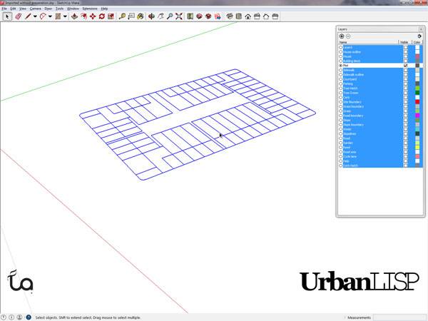
Working in SketchUp might be considered to be like working with chewing gum. Let’s say we import an AutoCAD drawing that is a bit further developed than Kevin’s plaza design into SketchUp. In this imaginary urban plan the plots are an important feature of our plan. In AutoCAD the plots are closed polylines and define areas. They are drawn on a designated layer. SketchUp fortunately also allows us to work with layers, very important as explained in the article “10 Must do’s to Become a Professional AutoCAD User”. When we check the layers in SketchUp we see that it adopted the layers we created in AutoCAD. Phew, that saved us some time! Now let’s turn off all layers except our plot layer. Huh? Where did our plots go? We can see some of it, but where’s the rest? As we can read at point 8 in Kevin’s “Top 10 Hints & Tips For SketchUp” we can select every connected entity by clicking an entity three times. When we do this we see a lot more than our remaining plots highlighted.
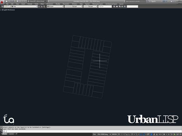
The plots in AutoCAD. Printscreen via Rob Koningen
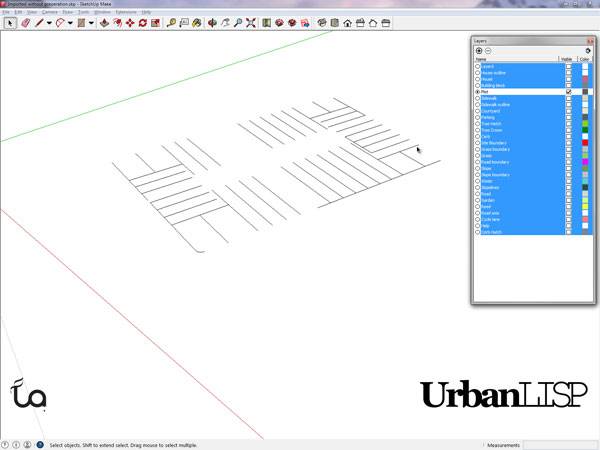
The plots in SketchUp. Printscreen via Rob Koningen
After clicking the plots three times. Printscreen via Rob Koningen
Isn’t something missing?
When we have another look at our imported drawing we see layers created and used for hatches in AutoCAD. But where did those hatches go? Well, they’re gone, as are your External References, by the way. The conclusion here – we don’t need those hatch layers so we can throw them out. Another additional action we have to do in addition to exploding our polylines and importing our layers one by one. Is there any time left for doing the actual design part? Probably not when you realize you also need to clear your blocks of useless hatches. Argh! Can you hear them too – those CAD opponents gearing up to bash the usage of CAD software? With all these issues you might consider joining them. Well, wait just a moment.
A Solution
The list of issues above was created over years of developing multi-layered masterplans and importing them into Sketch Up, working with models designed by colleagues that didn’t consider these issues and resulting in many frustrating hours of cleaning up the file. Of course our CAD programs are packed with useful tools but sometimes seem to lack the essential ones. As mentioned in the article “10 Must do’s to Become a Professional AutoCAD User” the usage of apps is essential to become a professional. Help the software you use help you. In this case you might want to check out the UrbanLISP command “Prepare for SketchUp”. Once you’ve loaded it into AutoCAD, all you have to do is type P-S-U and confirm you in fact want to do this. Please remember to save your AutoCAD file as a file to be imported and leave your original CAD drawing untouched; you don’t want to lose that information. Depending on the size of your drawing the command will run for up to ten seconds. It will give you time to take a sip of your coffee or look outside for a moment. Meanwhile, the command will do the following:
- It erases all layouts, you don’t need them in SketchUp anyway and they might contain layers or blocks that are not in the model space, that part that actually is imported into SketchUp.
- It detaches all xrefs, they will not be imported anyway.
- Same story for the hatches, they’re kicked out.
- Also any hatches are removed from your blocks.
- It explodes all polylines.
- It places all entities on the same layer in a block. Both AutoCAD and SketchUp work with groups but AutoCAD groups unfortunately aren’t considered as such by SketchUp. Blocks work in both programs, however. The new block will be a part of its own layer. Existing blocks will be excluded; they are already blocks.
- It purges the drawing; with the removal of all the useless entities listed above, you are bound to have some empty layers or blocks that aren’t used.
- It performs a regen as a conclusion. When the command is done, save the file and import it into SketchUp. The drawing will have strictly separated layers, beautiful round curves and you will have a clean file with only the layers that are in use.
The plots in SketchUp. Printscreen via Rob Koningen
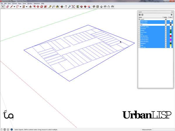
The plots are complete in SketchUp due to the ‘Prepare for SketchUp’ command. Printscreen via Rob Koningen
Recommended Reading:
- Digital Drawing for Landscape Architecture by Bradley Cantrell
- Detail in Contemporary Landscape Architecture by Virginia McLeod
Article by Rob Koningen
You can see more of Rob’s work at UrbanLISP


How to Create the Perfect Flow in Your Drawings – Video Tutorial
An AutoCAD tutorial on How to Create the Perfect Flow in Your Drawings from our resident AutoCAD expert UrbanLISP. Whether you are designing a path for a small garden or developing a master plan, chances are strong that you will draw a few lines that are curved. Creating these curves can be fairly easy, but there is more behind it than you might initially think. It’s good to know what to pay attention to, because it also easily can go wrong. And then things can get really awkward — if not disastrous. To prevent these situations, we are going to have a look at the science behind the curve. Before we talk about flows, we are going to have a quick look at two straight lines. When one straight line approaches another, both lines make an angle with each other. When this angle is exactly 90 degrees, it’s perpendicular. When they make an angle of 180 degrees, they actually don’t make an angle. In that case, they are parallel.
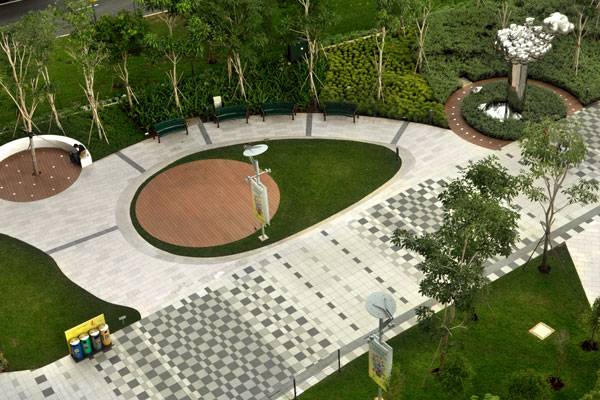
Creating seamless curves at City Square Urban Park. Photo credits: See Chee Keong
How to Create the Perfect Flow in Your Drawings
(No time to read the full article, scroll down to the video)
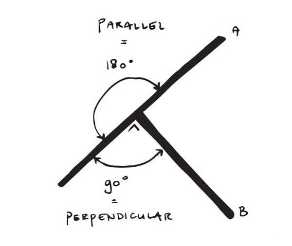
Image credit: UrbanLISP
Fillet
Now we understand perpendicular and parallel lines. Most CAD programs have a function to connect lines with a curve. In AutoCAD, this command is called fillet. When you use this command, you’ll create a perfect flow from one line to the other with an arc — a curve. The fillet command helps a bit by shortening or extending the lines we used for this flow. The arc it created is based on the geometry of these lines. The arc has a start, an end, and a center point. Let’s have a look at the position of those points. The fillet command extended or shortened the lines we selected based on the radius we defined. When we take the end point of each line that connects with the arc and draw a line perpendicular from it, those lines will cross each other at some point. And guess what — this is the center point of the arc that was created with fillet.

How would you go about making the curves in these walls? Baan San Ngam. Photo credit: Pirak Anurakyawachon
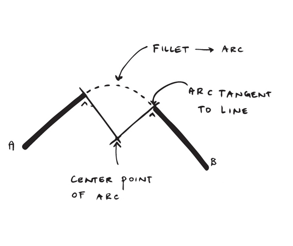
Image credit: UrbanLISP
What is Tangent?
If you have a hard time understanding tangency, try to imagine that you have a basketball and a plank. The basketball is on the ground, with the plank on top of it. You don’t have to balance the plank; one side can touch the ground. In essence, you’ve created a tangent flow. Imagine the plank is cut exactly on the point where it touches the basketball. It doesn’t matter how far the plank sticks out, the point where they connect will always be tangent.
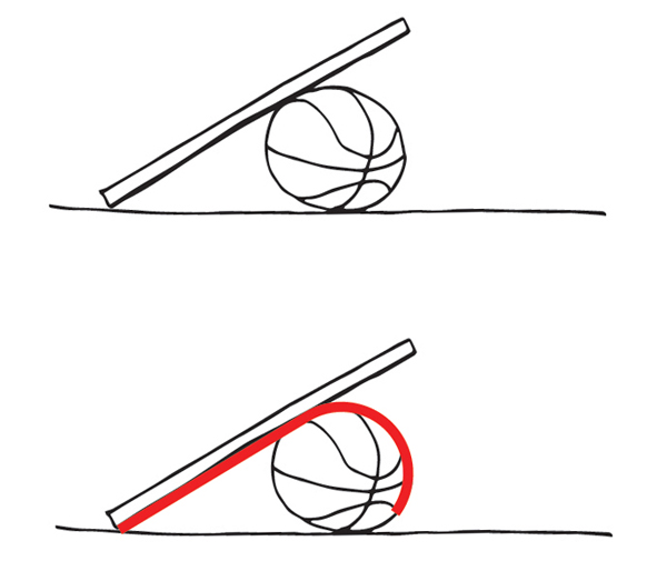
Image credit: UrbanLISP
The Circle Method
With fillet, AutoCAD takes a few actions out of our hands. You can essentially do the same thing with the circle command. When starting this command, there are a few options in the command line. One of them is TTR. It stands for Tan Tan Radius, which is short for Tangent Tangent Radius. When we use this option, the command will ask you to click a point on two different linear entities. It will use a special snapping mode called “deferred tangent” that will consider the point you’ve selected more like a search area than an exact point. After picking the points, you have to define a radius. The command will draw a full circle with a specified radius. The circle will be tangent to both linear entities you’ve clicked with the “deferred tangent” snapping mode. After that, it’s just a matter of trimming the circle and line, and you’ll have the same effect as fillet. There might be cases, however, when you don’t want the lines to be trimmed. In that case, this method is very helpful.
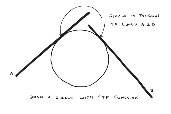
Image credit: UrbanLISP
Offset
When you work in a CAD program that doesn’t have a fillet command, the offset command could help you out. If you want to make an arc with a radius of 25 units, you can make an offset of the linear entities of 25 units and find the intersection point of those entities. Use that intersection point as center point for the circle you want to draw, and you’ll see the circle will be tangent to both original linear entities.
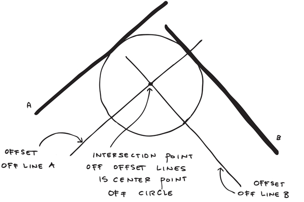
Image credit: UrbanLISP
The Other Way Around
Previous examples were with straight lines. Fortunately, fillet also works with arcs. It will extend or shorten them to fit a tangent arc. With three consecutive tangent arcs, there’s a real nice flow appearing.
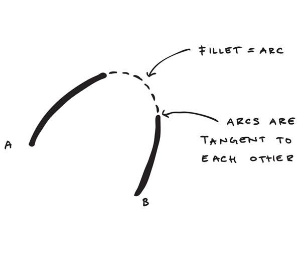
Image credit: UrbanLISP
- 4 AutoCAD Commands to Draw Paving Patterns on Curving Paths
- How to Show Topography in your Plan Drawing in AutoCAD
- How to Place Large Quantities of Trees in a Master Plan Instantly with AutoCAD
IN THESE EXAMPLES, we basically used fillet to create rounded corners between the entities we already had. But what if we already have those rounded corners and want to make the connections between them? If you want to create straight connections, you can use the line command. When picking the points, you can override the snap options to tangent snapping by typing “tan”.
Recommended Reading:
- Digital Drawing for Landscape Architecture by Bradley Cantrell
- Detail in Contemporary Landscape Architecture by Virginia McLeod
Do this for both points of the line and select a point somewhere on the circle. The line that will be drawn will be tangent to both circles. If you want to draw a rounded connection, you revert to the circle method and use the TTR feature.
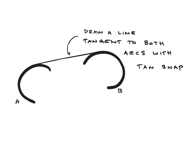
Image credit: UrbanLISP
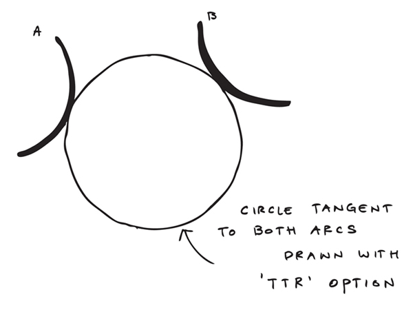
Image credit: UrbanLISP
Select a Single Entity
So fillet allows you to connect two linear entities with a curve. But what if you only have one entity? You’ll have one entity, so you know you want to be tangent to that one. But where to go? The UrbanLISP “Tangent Arc to Linear” command allows you to place a tangent arc as an extension of a linear entity. Where the arc goes is for you to decide. Start by selecting a linear entity. This can be any entity — a line, arc, or polyline, but even a spline or an ellipse. Select the entity on the side you want to place the arc; the command will take that side as base point. After that, it’s just a matter of aiming the arc and clicking in the drawing. You can do the same thing with the “Tangent Arced Segment”. If you use this command, you can select polylines. The arc you create will be added as a segment to the polyline.
Achieve Perfection
OK, we now know how to create a flow. But how do we make it perfect? If you are a student, you are probably only doing theoretical plans. Once you become a professional, you will develop plans toward realization. The more accurate your drawings are, the more serious engineers, constructors, and architects will be about applying it. If you draw a road with a radius of 24.78 units, it will not be welcomed with a lot of enthusiasm. Why not make the radius 25 units?

Curves at Cumberland Park. Photo credit: Hargreaves Associates

Maybe one day you’ll be planning curves like these ones at Zhangjiagang Town River Reconstruction. Image courtesy of Botao Landscape (Australia)
See the full tutorial on How to Create the Perfect Flow in Your Drawings:
–
Recommended Reading:
- Digital Drawing for Landscape Architecture by Bradley Cantrell
- Detail in Contemporary Landscape Architecture by Virginia McLeod
Article by Rob Koningen
You can see more of Rob’s work at UrbanLISP

The Art of Creating a Legend AutoCAD Tutorial
The Art of Creating a Legend AutoCAD Tutorial from our resident AutoCAD expert UrbanLISP. Creating a design is a process. It is highly recommended that you create a backup of your AutoCAD drawings every time you make a significant change in the design. This will allow you to revert back to a previous version in case the latest changes don’t seem to work out that well. At the end of the process, you shouldn’t be surprised to have up to 30 backups of your file. Needless to say, you will have spent a lot of time and effort. If you drew it properly, you know the meaning of every layer, block, and line. But then it is time to present it. And guess what? The people to whom you present the plan don’t know it as well as you do. They need a legend! Drawing in any CAD program requires consistency, as mentioned in the article ’10 must do’s to become a professional AutoCAD user’. If you are consistent, you will have proper layer and block names and have placed every entity on the layer where it should be. You likely worked right up until the deadline to present it – which doesn’t leave much time to create a legend.
Creating a Legend AutoCAD Tutorial
 Creating a legend can be tedious, because you know every little detail of the drawing already. But with the UrbanLISP ‘Quick Legend’ command, you can create one with just a few clicks. Like most CAD tools, it allows you to do something quickly. The end result is completely up to you. Before creating a legend, it is good to think about what should be in it. In order to determine what should be in it, it is good to realize that a plan drawing can be broken down into a few basic elements. Areas The most important elements of a plan drawing are areas. In AutoCAD, the areas can be defined by hatches. The hatches are the definition of each area, and together fill your entire plan drawing. The hatches will tell where grass, roads, bicycle paths, water, and slopes are. Objects In those areas are objects, and it is advisable to draw them as blocks in AutoCAD. Think of benches, lighting fixtures, drains, and bollards. When you insert them as blocks, you can move and copy them as one element. When you change the blocks, you change all of the blocks in your drawing. Linear Entities Lines, arcs, circles, polylines, splines, and ellipses are linear entities in AutoCAD. You can use them to draw a fence, a road axis, or utility lines. See these AutoCAD tutorials:
- 4 AutoCAD Commands to Draw Paving Patterns on Curving Paths
- How to Show Topography in your Plan Drawing in AutoCAD
- How to Place Large Quantities of Trees in a Master Plan Instantly with AutoCAD
The Gray Area Although adding a legend is often the last thing you do for a project, it is good to keep it in mind as you go through the design process. When setting up plan drawings, you will see that 80 percent of the basis is the same. But there are always exceptions. Take shrubs, for instance. For one project, you might want to define an area with shrubs. For the next, you might have a particular specie in mind and have a nice block for it. Or take a fence. In one plan drawing, you might want to draw it as a linear object; in the next, you might actually design a fence element and want to place it along that line. And what about utility lines? You may have detailed information about where the sewer, electricity, water, and gas lines are and have a specific line type assigned to each one. For another project, you may not have such detailed information, but know roughly where they go. Then, all of a sudden it becomes a zone, an area. Important Side Notes When you create a plan, think about the elements you want to use to build it. If you are in doubt, ask yourself the question: How do I want to quantify it? In the example of the fence, if you designed your own fence, you will want to know how much of the element you have used. If you only know where it should go, you may just want to know the total length and, in that case, draw it as a linear entity. And how do want to draw kerbs? You can draw them as a polyline with the desired width so you know the length you need. Or you can draw them as elements so you know how many elements you need. Or draw them as an area, because polylines with a width have their downsides and using blocks is too detailed. Then you know the area. When you divide the area by the width, you have the total length. When you divide the total length by the length of an element, you know the number of elements. So there are several ways to go about it. Consider the scale of the drawing and the size of your project and you may find your answer.
WATCH: Make Your Dawing a Legend AutoCAD Tutorial
Creating a legend might seem tedious, but it can also be helpful in building your plan drawing. It will certainly help you to explain the plan to your clients or teachers. The ‘Quick Legend’ command can help you to compile the legend. You can find it in the UrbanLISP app store; as long as it’s stamped with the social download stamp, it can be downloaded for free. Download it now and become a legend at creating legends.
Recommended Reading:
- Digital Drawing for Landscape Architecture by Bradley Cantrell
- Detail in Contemporary Landscape Architecture by Virginia McLeod
Article by Rob Koningen
You can see more of Rob’s work at UrbanLISP


Turn Useless Objects into Gold: Give Your AutoCAD Drawing a Makeover
Turn Useless Objects into Gold from our resident AutoCAD expert UrbanLISP to make your work in AutoCAD more efficient. After the conceptual phase during which you make a lot of sketches, it’s time to get real. A good drawing of the existing situation of the site is essential for making a proper plan drawing. Although AutoCAD is the industry standard for these drawings, when working on projects across the world, it becomes clear that there is no standard on how information is organized. So you will have to work with the information you get. Take trees for instance. The way they are represented is quite essential to your drawing. But if you only receive points for the tree locations, you are far off from a nice plan drawing. It’s easy to place a block on a point. Just make sure you snap to the node of the point. If you work on a site of a few square kilometers, however, it becomes a different story. You might have a few thousand points on which to place a tree. As mentioned in the article ’10 must do’s to become a professional autocad user’, drawings are essentially graphical representations of databases. Perhaps the term big data rings a bell? The databases are packed with useful information. If you know how to access those databases, you can turn useless objects into gold. See these AutoCAD tutorials:
- 4 AutoCAD Commands to Draw Paving Patterns on Curving Paths
- How to Show Topography in your Plan Drawing in AutoCAD
- How to Place Large Quantities of Trees in a Master Plan Instantly with AutoCAD
Point to Block The bare minimum you can find as specification for a tree location is a point. Of course, there is a lot more information you might want to have for a tree. If you are missing the location, it’s impossible to place a tree. With the ‘Point to Block’ command, it’s easy to turn all the points in your drawing into blocks. Line to Block A point is a one-dimensional object; essentially, just a location. A line is two-dimensional and gives us more information. With the ‘Line to Block’ command, we can use that information. A line has two points: a start point and an end point. Those points give us valuable information. We can use either one of those points to place a block. But when you know these points, you also know the midpoint. So that’s three points we can potentially use to place a block. But let’s take it one step further. When you have two points, you also have a distance. That’s information, as well. So when we place a block on a line, we have three options for the placement and the option to scale it; we just relate it to the distance. Circle to Block Lines aren’t the only linear entities we can use. Circles also contain information that allows us to place a block. If you only have arcs in your drawing, don’t worry. Arcs are essentially circles that aren’t closed. So if you want to have circles instead, you can use ‘Arc to Circle’ and all your arcs will turn into circles in no time. A circle is essentially defined by two values — the center point and the radius. With ‘Circle to Block’, we can place a block on the center point and relate the scale to the radius. Block on Text Sometimes site drawings show the location of the tree as text. The content of the text is often related to the species. With the ‘Block on Text’ command, it’s possible to select text entities and place a block on them. By selecting the text entity with the proper content, you can place different blocks on different contents and place species-specific blocks on the text. WATCH: Our YouTube Video for this Tutorial
These are a few very basic metamorphosis tools from the UrbanLISP app store to turn your CAD file into a representable drawing. Information can be provided in many different ways and in different formats. Even an Excel file with a tree inventory can be very useful and can be imported to a drawing. We live in an age of big data. If you know how to access and use that data, you can turn something that seems useless into gold.
Recommended Reading:
- Digital Drawing for Landscape Architecture by Bradley Cantrell
- Detail in Contemporary Landscape Architecture by Virginia McLeod
Article by Rob Koningen
You can see more of Rob’s work at UrbanLISP


5 Easy Steps to Mess Up Your AutoCAD Drawing … and Make it Look Better
5 Easy Steps to Mess Up Your AutoCAD Drawing … and Make it Look Better from our resident AutoCAD expert UrbanLISP to make your work in AutoCAD more efficient. With landscape architecture, we try to shape and organize spaces with trees, plants, water. In other words, we work with nature. When developing a plan in AutoCAD, we work with a computer — just about the opposite of nature. How do we make something look like nature with something that is the opposite? Well, we can randomize! In a previous article, you can read how to do this in sections. In each of the following steps, we use a tool to approach a natural look with trees by randomizing in plan view. WATCH: 5 Easy Steps to Mess Up Your AutoCAD Drawing … and Make it Look Better
We start with a drawing with tree blocks. There are blocks in a grid, which is easy to draw in AutoCAD, and a few blocks representing a variety of species. In the top left corner, there are hatches with different colors.

0_start
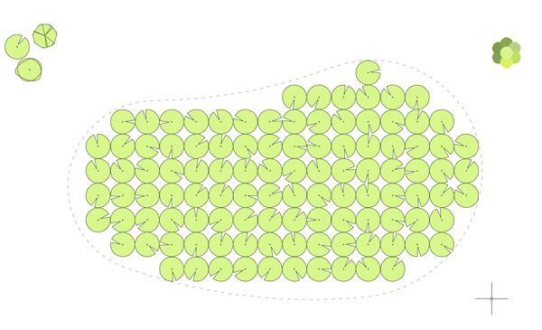
Rotate random
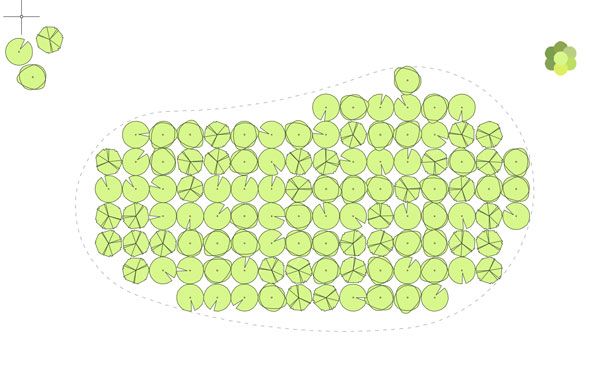
Exchange random
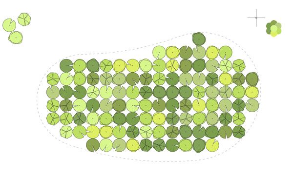
Colour random

Scale random
- 4 AutoCAD Commands to Draw Paving Patterns on Curving Paths
- How to Show Topography in your Plan Drawing in AutoCAD
- How to Place Large Quantities of Trees in a Master Plan Instantly with AutoCAD
You will never find such a row in real life. And with a 3d model, you want to approach real life. One way is to create variations of the 3d tree you have. Creating one 3d tree with leaves is already time-consuming, however. To prevent getting stuck in “designing” trees, you can simply apply “Rotate Random” and “Scale Random” to the blocks before you import them into SketchUp.
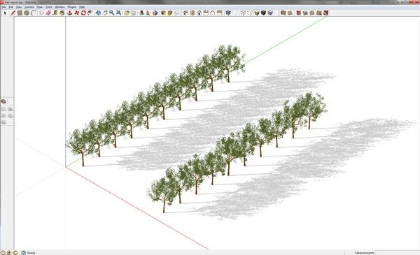
Tree import SketchUp
Recommended Reading:
- Digital Drawing for Landscape Architecture by Bradley Cantrell
- Detail in Contemporary Landscape Architecture by Virginia McLeod
Article by Rob Koningen
You can see more of Rob’s work at UrbanLISP


10 Must do’s to Become a Professional AutoCAD User
10 top tips from our resident AutoCAD expert UrbanLISP to make your work in AutoCAD more efficient. When drawing by hand, we use a box of pencils, crayons, a ruler, and maybe a compass. Whatever we use, it’s all on our desk, in sight and ready to grab. AutoCAD is stuffed with functionalities hidden in menus, on palettes, and behind shortkeys. In order to get the most out of AutoCAD, we list the 10 must do’s to become a professional AutoCAD user: 1. Layers, layers, layers Without a doubt, one of the most important aspects in a drawing is the use of layers. An empty drawing by default only has one layer, named “0” in AutoCAD. Don’t use this layer unless you know what you are doing; it behaves in a particular way. It’s hard to create too many layers, but to prevent getting lost, it’s wise to think of a layer structure first. Add numbers for main categories as a prefix of the layer names so they are grouped together in the layer menu by default. As suffix, it’s good to add a code related to the type of object it’s used for; -b for layers that are boundaries, -h for layers with hatches, -t for layers with only text. You’ll get layers like 012-grass-b and 012-grass-h.
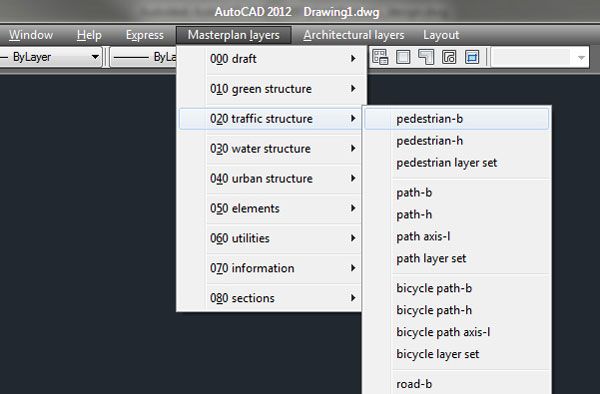
Layer pulldown menu
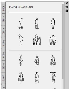
Blocks on toolpalette
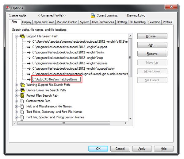
Hatch patterns_add path
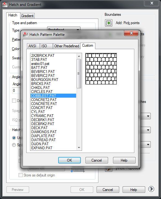
Hatch patterns_custom
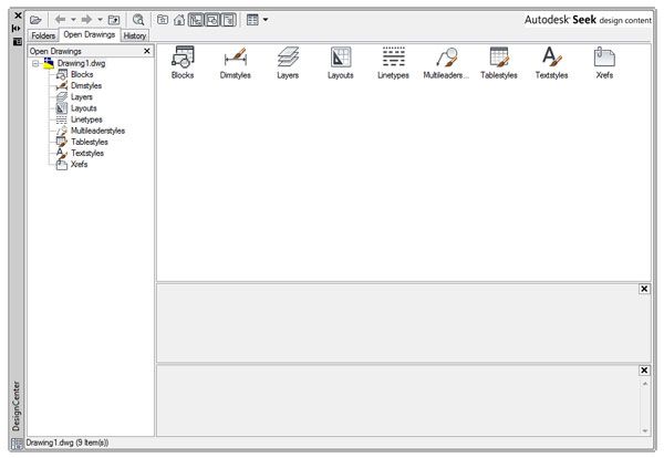
Design Center
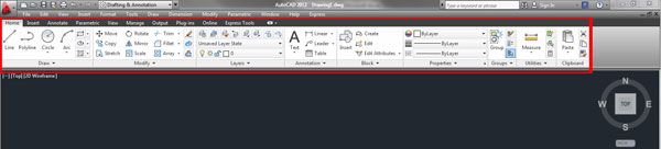
Ribbon
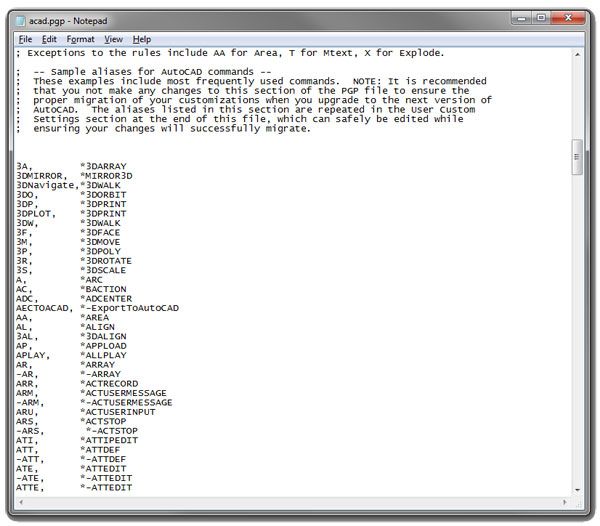
Acadpgp
- 4 AutoCAD Commands to Draw Paving Patterns on Curving Paths
- How to Show Topography in your Plan Drawing in AutoCAD
- How to Place Large Quantities of Trees in a Master Plan Instantly with AutoCAD
9. Snap and select like a pro There are two main purposes for the mouse in AutoCAD: defining positions and selecting objects. If you want to draw accurately, snapping to the right point is extremely important. It sounds obvious, but it deserves some attention. The more objects in your drawing, the more snapping points you’ll have. If there are a few snapping points close to each other, the chance of snapping to the wrong point increases:
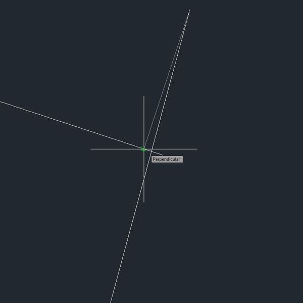
Snap perpendicular
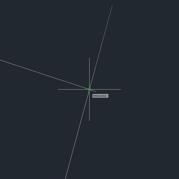
Snap intersection
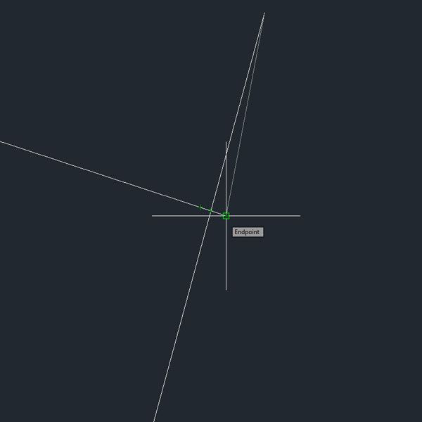
Snap endpoint
Selection crossing
Selection_window
Selection_crossing polygon
Selection_dragging
Selection_fence
Recommended Reading:
- Digital Drawing for Landscape Architecture by Bradley Cantrell
- Detail in Contemporary Landscape Architecture by Virginia McLeod
Article by Rob Koningen
You can see more of Rob’s work at UrbanLISP

4 AutoCAD Commands to Draw Paving Patterns on Curving Paths
A useful AutoCAD tutorial from our resident AutoCAD expert UrbanLISP to help you with drawing paving patterns on curving paths. You can hatch objects in AutoCAD with default paving patterns. Considering the amount of paving materials available, it’s fair to say these hatches are a bit limited for landscape architects. It’s possible to create custom hatch patterns, but one problem will remain; hatch patterns are continuous patterns. That’s fine when you’re drawing, for instance, a herringbone pattern, a pattern that doesn’t change when it’s on a curving path. Stretcher bond and running bond can both follow gentle curving paths. In this case, the pattern is build up out of one size element that alternates every strip with half a stone. If you want to have a more playful look you can use a wild stretcher bond or a wild running bond pattern with random size elements. The patterns are buildup out of linear entities so you can trim out and extend the pattern where you want. You can find these AutoCAD commands in the UrbanLISP app store. As long as they are stamped with the social download stamp you can download them for free and try them out. WATCH the Full Tutorial Here:
Recommended Reading:
- Digital Drawing for Landscape Architecture by Bradley Cantrell
- Detail in Contemporary Landscape Architecture by Virginia McLeod
Article and video tutorial by Rob Koningen
You can see more of Rob’s work at UrbanLISP


How to Place Large Quantities of Trees in a Master Plan Instantly with AutoCAD
LAN Tutorial: How to Place Large Quantities of Trees in a Master Plan Instantly with AutoCAD expert Rob Koningen. Placing a tree in a design for a garden is an entirely different task then placing trees in a design for a master plan of a few hectares. For a garden design, you pick the positions carefully; for a master plan, you may just need sheer quantity, roughly placed. And when that deadline is approaching, you may need to place them quickly. In this article, you will learn two ways to place trees — and place them fast.
How to Place Large Quantities of Trees
Sweep Your Mouse

Image courtesy of Rob Koningen
- How to Show Topography in your Plan Drawing in AutoCAD
- How to Add Detail to Your Sections in AutoCAD
- How to Randomise Hatches in Your AutoCAD Drawing
Pick Points

Image courtesy of Rob Koningen
Recommended Reading:
- Digital Drawing for Landscape Architecture by Bradley Cantrell
- Detail in Contemporary Landscape Architecture by Virginia McLeod
Article and video tutorial by Rob Koningen You can see more of Rob’s work at UrbanLISP Return to Homepage


How to Add Detail to Your Sections in AutoCAD
A useful AutoCAD tutorial to help you with detailing your sections in AutoCAD. Plan drawings could be considered the most important graphic of a landscape architecture project. Sections and elevations, however, also explain a lot and are important during the design process. Drawing natural elements in elevation requires a different approach than drawing them in plan. Take grass, for instance. In a plan drawing, grass can be represented as a dotted hatch or maybe even a green solid hatch. This doesn’t work in section. In this article, you’ll see some cool and quick ways to draw nature in no time. The problem of the traditional method A lot of AutoCAD users draw grass in sections with a block. Of course, this is an option, but it has some downsides. A block always has a particular size. Let’s say you have a block that stretches over one meter of surface. If you want to place the block on a line that is 3.5 meters long, you will have to shorten that block. You will have to explode it and delete some entities or xclip the block. And that’s assuming you are placing it on a straight line. Since landscape architects like to play with topography sometimes, you need to draw grass on a curving base — another challenge when you draw grass with blocks.
Sections in AutoCAD
Select the baselines The space where grass needs to be drawn in a section can be defined by a linear entity. In the included video, you will see how the commands ‘Grass In Elevation’ and ‘Reed In Elevation’ allow you to draw natural entities in an instant by selecting linear entities. No blocks are required.
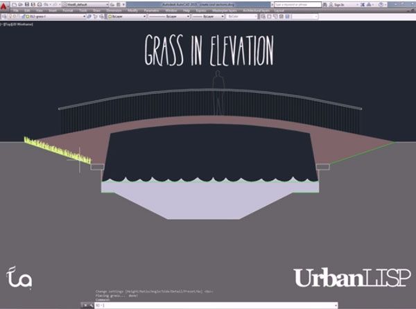
Grass in elevation
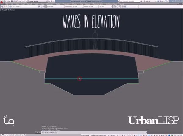
Waves in Elevation
- How to Show Topography in your Plan Drawing in AutoCAD
- How to Randomise Hatches in Your AutoCAD Drawing
Send in your vegetation patterns The UrbanLISP commands in this article are part of the elevation category. If you often use a particular vegetation pattern in your drawings and you think it could be nice if it would work in the same way as the commands shown in the video, please send an example! Most patterns can be translated into a script to automate the drawing process, and if your pattern is suitable, it can be a nice addition to the elevation category. Of course, you will be the first one to test it! Native AutoCAD features Besides the elevation commands, you can also see a few native AutoCAD commands and tricks in the video. Did you know you don’t have to use your mouse to make a selection? Or that you can create a closed polyline based on linear entities in your drawing by using the ‘Boundary’ command? Check the video and see how it works. Enjoy! WATCH: Tutorial on How to Add Detail to Your Sections in AutoCAD
Recommended Reading:
- Digital Drawing for Landscape Architecture by Bradley Cantrell
- Detail in Contemporary Landscape Architecture by Virginia McLeod
Article and video tutorial by Rob Koningen You can see more of Rob’s work at UrbanLISP Return to Homepage


How to Randomise Hatches in Your AutoCAD Drawing
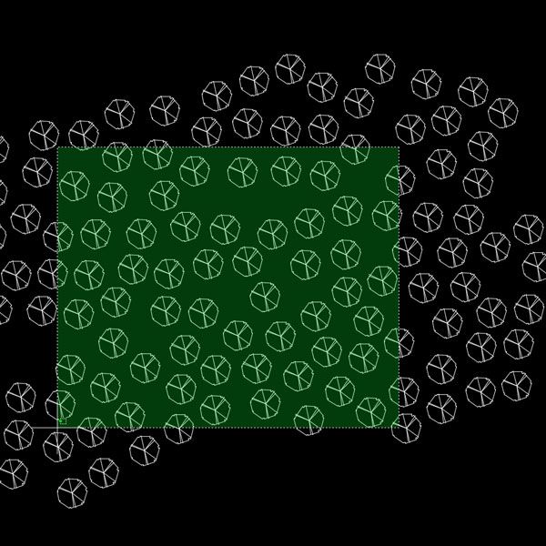
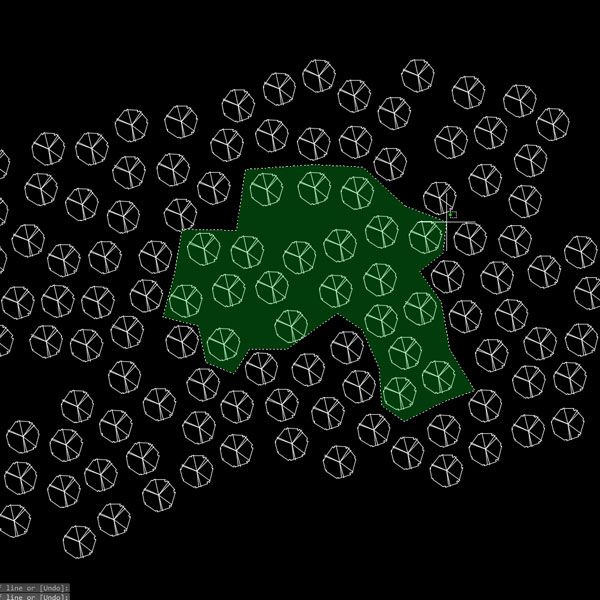
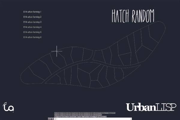
LAN Tutorial: How to Randomise Hatches in Your AutoCAD Drawing with AutoCAD expert Rob Koningen. As no human being is the same no human being will organise their surrounding in the exact same way. Although people may live in a house which looks the same as their neighbour’s, any open space belonging to it, be it a balcony, patio or garden, is designed or decorated in a different way. When drawing an urban plan it’s nice to express this somehow.
Randomise Hatches in Your AutoCAD Drawing
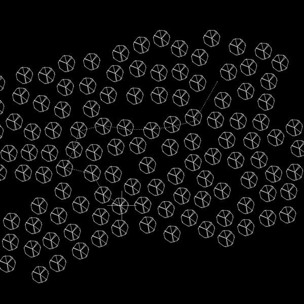
To show a variation of gardens without having to draw the entire garden in urban plans the ‘Hatch Random’ command was created. It works really simple. You have to prepare some layers, as many as you like, and assign different colours to each layer. In your drawing, you apply these layers to a few entities so you can select them. Then you have to create closed polylines for the garden areas.
See the full tutorial below!
- How to Show Topography in your Plan Drawing in AutoCAD
- 10 AutoCAD Hacks for Beginners!
- 3D Modeling Software for Landscape Architects
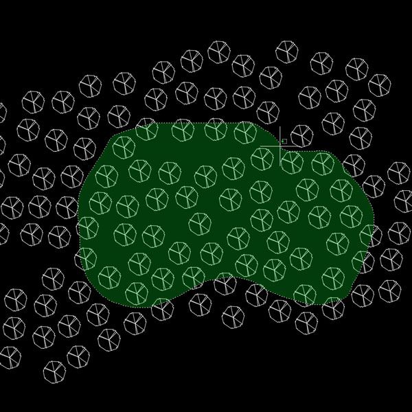
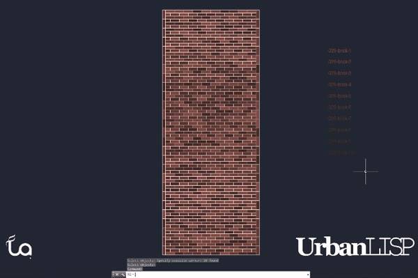
For every solid hatch, the command will choose a layer from that palette randomly. Although the command was initially created to hatch gardens, it can be used for any feature that needs a variation in colour. Think about a brick path for instance. Bricks can come in a variety of colours and when you are drawing a detailed plan drawing it can be nice to show this.
See the full tutorial below!
Randomise Hatches
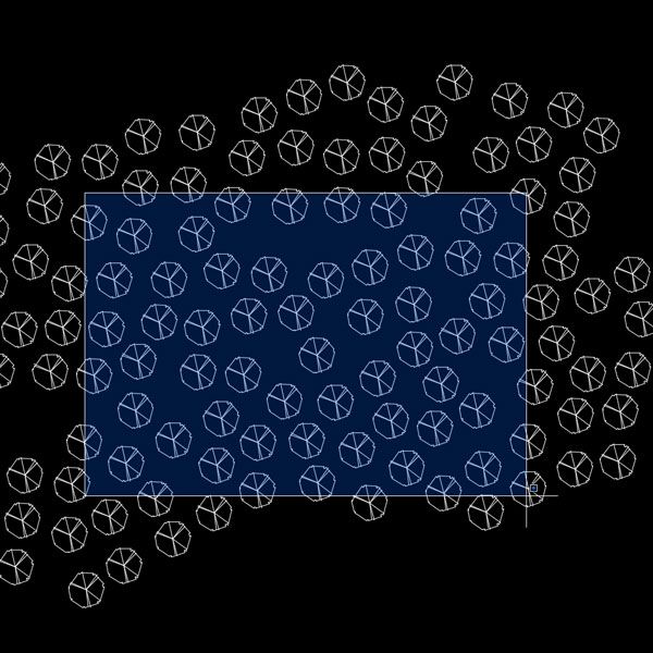
Another way, to play with hatches in your drawing, is by randomising the patterns. With ‘Hatch Pattern Random’ you can select solid hatches, after which you can select hatches with any kind of pattern you like. Instead of making a palette of colours, like with ‘Hatch Random’, you make a palette of patterns.

See the full tutorial below!
- Digital Drawing for Landscape Architecture by Bradley Cantrell
- Detail in Contemporary Landscape Architecture by Virginia McLeod
Article and video tutorial by Rob Koningen You can see more of Rob’s work at UrbanLISP Return to Homepage


How to Show Topography in your Plan Drawing in AutoCAD
A useful AutoCAD tutorial to help you with topography lines in AutoCAD. Computer aided design (CAD) software doesn’t come up with great concepts, as pointed out well by Barry Lupton. However in pretty much every project you reach a point where you want to digitalise sketches. Amongst others AutoCAD is probably the most used CAD program in landscape architecture and many other professions. As it is an extremely extensive program, only a few use it to it’s full potential. Even though you create drawings with it, it’s nothing like a box of pencils from which you pick the color you want just by looking at the box. You need to find your way. And it doesn’t stop there. AutoCAD can be customized and extended in virtually endless ways. So some pointers may come in handy! Lisa Tierney showed us 10 basic AutoCAD hacks, a useful overview for the absolute beginner. This article is the first of hopefully many about AutoCAD functionalities that, even when you are a pro, you may never have realized were possible. This first post from UrbanLISP is about topography in plan drawings.
Topography in your Plan Drawing in AutoCAD
Sections are very useful to show topography and slopes. Plan drawings still are the most important images you will produce during a project. Of course the topography should be shown in that plan drawing. In many countries it’s common to draw slope lines. It’s a pattern of lines that go from the top of the slope to the bottom. Every second line ends one half of that distance. Drawing such a pattern in AutoCAD on straight lines is not too much work. When the slopes in your plan are curvy the challenge is a bit bigger. The UrbanLISP ‘Slopelines’ command helps you to place such a pattern in an instant. Related Articles:
- Top 10 Hints & Tips For SketchUp
- 10 AutoCAD Hacks for Beginners!
- 3D Modeling Software for Landscape Architects
You only have to select two linear entities. Polylines, lines, arcs and splines are examples of linear entities. You have to select one for the top and one for the bottom and the pattern will be drawn in between. You can tweak the settings of the command to get an optimal result depending on the curves you use and the units your drawing is set to.
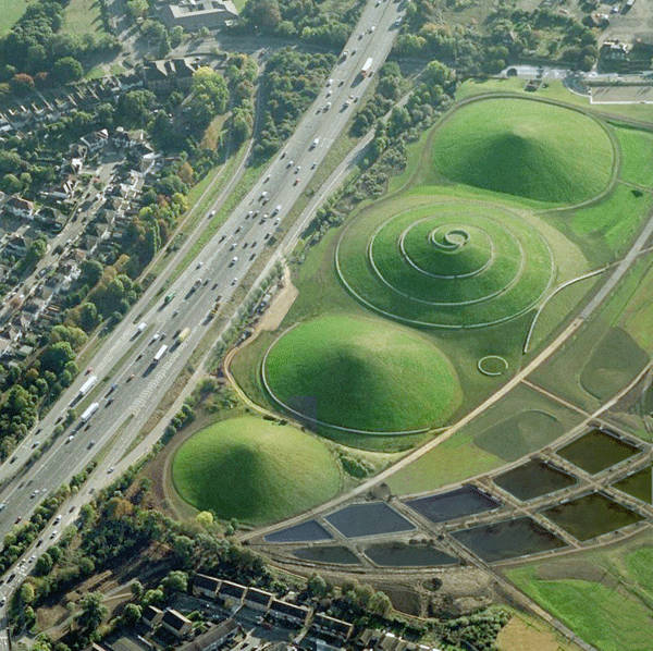
Where topography lines would come in handy. Photo credit: Northala Fields by Peter Fink and Igor Marko
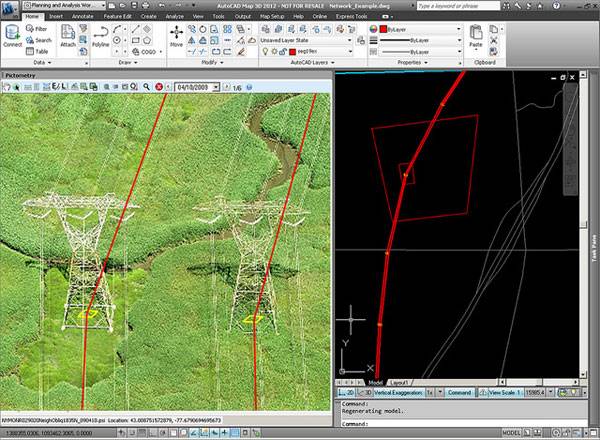
Image featured in our article “Computer Aided Software for Landscape Architects: The Essential Guide”. Image credit: @gletham GIS, Social, Mobile Tech Images; CC2.0
- Digital Drawing for Landscape Architecture by Bradley Cantrell
- Detail in Contemporary Landscape Architecture by Virginia McLeod
Article and video tutorial by Rob Koningen You can see more of Rob’s work at UrbanLISP Return to Homepage