


A useful AutoCAD tutorial to help you with topography lines in AutoCAD. Computer aided design (CAD) software doesn’t come up with great concepts, as pointed out well by Barry Lupton. However in pretty much every project you reach a point where you want to digitalise sketches. Amongst others AutoCAD is probably the most used CAD program in landscape architecture and many other professions. As it is an extremely extensive program, only a few use it to it’s full potential. Even though you create drawings with it, it’s nothing like a box of pencils from which you pick the color you want just by looking at the box. You need to find your way. And it doesn’t stop there. AutoCAD can be customized and extended in virtually endless ways. So some pointers may come in handy! Lisa Tierney showed us 10 basic AutoCAD hacks, a useful overview for the absolute beginner. This article is the first of hopefully many about AutoCAD functionalities that, even when you are a pro, you may never have realized were possible. This first post from UrbanLISP is about topography in plan drawings.
Topography in your Plan Drawing in AutoCAD
Sections are very useful to show topography and slopes. Plan drawings still are the most important images you will produce during a project. Of course the topography should be shown in that plan drawing. In many countries it’s common to draw slope lines. It’s a pattern of lines that go from the top of the slope to the bottom. Every second line ends one half of that distance. Drawing such a pattern in AutoCAD on straight lines is not too much work. When the slopes in your plan are curvy the challenge is a bit bigger. The UrbanLISP ‘Slopelines’ command helps you to place such a pattern in an instant. Related Articles:
- Top 10 Hints & Tips For SketchUp
- 10 AutoCAD Hacks for Beginners!
- 3D Modeling Software for Landscape Architects
You only have to select two linear entities. Polylines, lines, arcs and splines are examples of linear entities. You have to select one for the top and one for the bottom and the pattern will be drawn in between. You can tweak the settings of the command to get an optimal result depending on the curves you use and the units your drawing is set to.
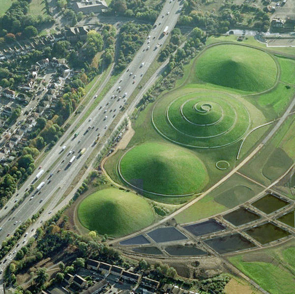
Where topography lines would come in handy. Photo credit: Northala Fields by Peter Fink and Igor Marko
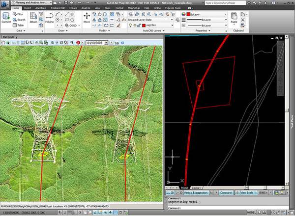
Image featured in our article “Computer Aided Software for Landscape Architects: The Essential Guide”. Image credit: @gletham GIS, Social, Mobile Tech Images; CC2.0
- Digital Drawing for Landscape Architecture by Bradley Cantrell
- Detail in Contemporary Landscape Architecture by Virginia McLeod
Article and video tutorial by Rob Koningen You can see more of Rob’s work at UrbanLISP Return to Homepage
Published in Blog


Pingback: Autocad Topography From Points