


Author: Nicholas Buesking


Software Review: Vectorworks
In one of my previous posts, I took a look at the promise of Vectorworks software for landscape architecture. I was impressed by the host of features the software has to offer through its multiple platforms: basic 2D/3D modeling with Fundamentals, landscape-specific tools with Landmark, and slick output with Renderworks. On top of these, the software utilizes a BIM approach to improve understanding of design decisions and coordination with related professionals in order to better steer final outcomes. It is aiming to place tools in the hands of landscape architects to design and interact on the same level as our architect counterparts. I have spent a fair number of hours learning Vectorworks and getting used to how it handles in order to assess how well the software delivers. The article contains a large amount of information, so to view a particular topic use the navigational structure below.
Basic Modeling – File structure | 3D Considerations | File Sharing
BIM Functionality – Implementation | Grading | Smart Objects | Planting | Irrigation | Drainage | Worksheets
Output – Construction Documentation | Rendering
What’s New to Vectorworks 2017

A well developed model can quickly be utilized to create plans, construction details, and photo-realistic renderings. Image credit: Nicholas Buesking
The first essential aspect of the program is 2D drafting and 3D modeling. Vectorworks behaves like a mashup of Rhinoceros and Sketchup. Vectorworks is tool-based like SketchUp rather than command-based like AutoCAD or Rhino. The available tools provide simple geometry creation for efficient drafting, yet there are a host of tools that enable highly complex and accurate shapes. Objects are each assigned a layer and a class. “Classes” act like AutoCAD’s layers while “layers” are a meta-structure that help separate overlapping aspects of the design, such as hardscape, site grading, and planting. The dual system allows for powerful control of visibility in a 3-dimensional model; however, establishing and following a strict layer/class protocol is essential because without management the file can become cluttered, requiring tedious post hoc correction. One Vectorworks user related that designers in his office dislike working in their coworkers’ files because each handles the layer/class system differently. This is not a problem with Vectorworks itself, but an issue inherent in any drafting program, amplified by the dual system. In its favor, Vectorworks attempts to help manage the issue by auto-classing a number of objects, such as dimensions or plug-in object components.
The program handles 3D space fluidly, if not always intuitively. Each layer is assigned an elevation on which objects are placed as default but can be moved. Locations of objects on the Z axis are stored in relation to the layer elevation, which can lead to confusing jumps in geometry when changing an object to a different layer. Vectorworks employs a clever use of “working planes” to override default elevations and constrain geometry creation intuitively. For example, in a top or side view Vectorworks drafts only on the visible plane based on a snapped starting point. Additionally, the program has zoom and x-ray functions to provide greater precision when acquiring snap points. Together, these eliminate many of the frustrations in other 3D modeling programs caused by the time consuming process of selecting the correct snap point by navigating the model. On the other hand, objects buried below others can become extremely difficult to select, especially when they align with another object. Vectorworks supplies no easy way to select overlapping objects through an object selection window, like the ones found in AutoCAD and Rhino. Likewise, Vectorworks does not have a typical isolation mode, though you can control the view and editability of non-active layers and classes. These settings can be preserved in a “saved view” for quick toggling between commonly needed layer/class settings. The ability to isolate several classes quickly to perform specific tasks and then restore the previous visibility state would be a nice feature but Vectorworks’ other visibility features limit the need.
A strength of Vectorworks’ modeling interface is that there are frequently multiple ways to create objects based on a user’s natural workflow. For example, hardscape objects can be created via drawing the geometry directly with the Hardscape Tool or converted from an existing polygon drawn during the concept phase. Unfortunately, the result is a large number of tools that are not always in intuitive locations. In fact, one of my biggest frustrations as I learned to use Vectorworks was the number of tool choices and their configuration. Important options can be buried within contextual tool palettes or hidden in tool settings. The information embedded into each object and different tool options can make troubleshooting difficult.
Vectorworks allows for project files to be shared easily with other offices and disciplines. It can be exported to a DWG or DXF file for coordination with civil engineers or architects, and Vectorworks 2017 can now import files directly from a Revit format. Feedback that I have heard from users has been that the process is painless as long as the workflow is coordinated. In the case of an engineer, it generally means drafting from the coordinate system the engineer is using so that the model will import into the expected place and not require shifting upon receipt.
Overall, once you understand the interface, have a good file management protocol, and have the right resources at your fingertips, modeling becomes a smooth process. The basic drafting tools, however, are by no means what makes Vectorworks stand out. Rather, it is its impressive array of ever-growing BIM tools geared towards landscape architecture.

Sketch style renderings are great for conceptual-level presentations, giving the client a vision of the proposed design without being too detailed or too regimented. Image credit: Nicholas Buesking
Working in a 3D workspace with BIM data means resource investment. At initial implementation, creation of a company-wide database of drawing templates and resources libraries, which include plant objects, textures, render styles, and other symbols is imperative. While it may sound daunting, a number of practitioners with whom I have spoken indicated that, between Vectorworks’ existing resources and the ease of implementing new custom resources, adopting Vectorworks did not cause a major disruption in the company’s production. Additionally, more resource investment is required to establish an existing model at the start of each project; however, between a rich resource library and Vectorworks’ BIM capabilities, projects can be run more efficiently with greater control over design goals and product.
One of the most essential aspects of Vectorworks’ BIM functionality is its grading tools. Through a series of elevational source data inputs, Vectorworks constructs an existing digital terrain model (DTM) complete with interpolated contours, labels, and flow arrows. Generating the existing terrain data is easy. Three dimensional points or contours from a survey can be imported into Vectorworks from a host of file formats, or the data can be entered manually from field notes. During the design process, parametric site modifiers can be inserted and classified as “proposed” to affect the DTM. The modifier tools Vectorworks offers provides functionality that reflects the needs of designing a site. Contours provide the most standard approach but are nonetheless effective. Pads are extremely useful for creating sloped or non-sloped planar surfaces and is also integrated into the Hardscape Tool. There is an option to create retaining edges around pads for terraces and walls. Most of these tools function smoothly, but a few are cumbersome, requiring important data to be set only after object creation through the use of drop down menus and input fields.
Due to the nature of inputs the DTM receives and the need to interpolate, proposed grading plans can initially lack smoothness, with contours taking on a disjointed appearance. This may be an issue with the underlying calculation metric of the program, but I suspect much of it is a factor of the specific modifier inputs to which the DTM must respond. As a result, the grading plan may need refinement in order to deliver the level of artistry landscape architects desire. At the moment, Vectorworks does not provide an organic site modeling tool, such as SketchUp’s plugin sandbox, for such refinement. The Vectorworks team has confirmed that they are working to develop a more fluid process of interactive terrain modeling at the wish of Vectorworks users. We should expect to see that wish granted soon. For now, utilizing the contour tool to overwrite and smooth the auto-generated proposed contours is the best method. Because the site model is a part of the BIM workflow, it tracks both existing and proposed conditions, which allows for a real-time understanding of cut and fill needs. Bryan Goff, director of Design + Sciences for Grey Leaf Design, Inc. and long-time Vectorworks user, said that his company used Vectorworks’ cut/fill capabilities on a large residential project in Minnesota to move over 7,000 cubic yards of soil successfully on site without hauling away or importing any soil.
To complement the site model, Vectorworks has a host of smart objects. Smart objects contain information and editability far beyond the standard object in Vectorworks. The foremost is the Hardscape Tool. From it, surfaces such as patios, walkways, and gravel pads can be created. Some users even use it for sod. They can be given styles to detail base, leveling course, and pavements. Oddly, however, the styles are difficult to find and edit, and they are not integrated with other hardscape settings such as rendering options. Hardscape textures can be problematic too, conflicting with the site model if the hardscape object is used as a site modifier unless another smart object is generated to control appearance. Both these issues are advanced use of the software, but they fall within the workflow of effective BIM process and output. Another common tool is walls. They can be assigned particular assemblies, which is useful for landscape walls, building walls, and even foundations. Walls can also be stepped at the top and bottom to accommodate changes in grade. Unfortunately, horizontal-based objects such as coping and foundations cannot currently be combined with the main wall. They must be created as separate objects. Similarly, the stair tool provides a large range of functionality and control over stair objects, but there are limitations. The tool cannot support one to two riser steps nor can it create curved/L-shaped steps. In these cases, non-smart objects must be created.

Because plant objects have a 2D and 3D component to them, all that is required to move the 2D planting plan into a 3D representation is switching into a perspective view. Masses of plants can be given a more natural look with an automatic rotation option, which was not implemented in this rendering. Image credit: Nicholas Buesking
Another important category is the planting tools. Planting tools are the most common set of landscape tools found in other software packages. Vectorworks’ planting tools perform like a well-oiled machine. They allow you to place singular plants, rows, clusters, or groups of plants. One tool creates landscape areas that can contain multiple species, useful for specifying seeding mixes. Placed plants are automatically sent to the surface of the DTM. All of the parameters used when placing plants are stored and can be modified after creation so changes in design require only quick adjustments rather than laborious re-drawing. Once in the model, plants can be replaced either individually or as an entire species. Existing trees can be placed with embedded data such as species, size, label, current condition, and removal/protection instructions. Auto-generated classes in the plant symbols such as fill, bloom color, interior linework, and outline provide a high level of control over the 2D display of the plants. Tags for the plants are automatically generated and can be easily organized through a specialized distribution tool. The plant schedule can be generated with a single click. Every plant object has a 2D shape, a 3D visualization, and source data associated with it. Vectorworks comes with a pre-packaged set of 168 configured species-specific plant symbols and even more generic symbols. Vectorworks also has an extensive database from which to draw information during new plant object creation, which simplifies the process of creating a fully-developed plant object. Once developed, an office’s library of plants will remain relatively stable, with only periodic updating required.
With Vectorworks 2017, the company is showcasing its commitment to upgrading the landscape aspect of its BIM functionality. It is premiering an irrigation toolset within the Landmark module. Its capabilities include zone planning, water budgeting, hardware and pipe placement, coverage mapping, and flow calculations. Vectorworks worked closely with many of the industry-standard manufacturers to provide real specs on hardware. Bryan Goff raved about these new tools, saying, “Irrigation tools in Vectorworks 2017 offer the easiest, fastest, most accurate system I have worked with, giving us a MASSIVE competitive advantage in the market.” I do not doubt these tools will require refinement, but they promise to be a boon to anyone who deals with irrigation design due to their integration into the BIM workflow.
The new irrigation component of Landmark is an exciting addition to the landscape BIM toolset of Vectorworks.
One key functionality that is notably missing from Vectorworks is drainage design as it is a huge aspect of landscape architecture. Resources for specific hardware such as catchment basins are available, but Vectorworks does not have specific tools to deal with drain tile layout and design. The Vectorworks team has indicated that its users have not yet indicated a strong desire for such a module. As a result, drainage design must be adapted to a low level of BIM functionality, with simple objects representing drainage structures. Alternatively, a few plug-in products exist to address civil-oriented needs, including sewer and water lines.
The key of BIM is to use the data residing in the model to create a deeper, more accurate understanding of the design. Vectorworks uses worksheets to organize, analyze, and visualize the information collected within the model. They are spreadsheets that operate similar to Excel documents, but they have the advantage of linking to data directly in the model rather than need manual input. A worksheet can be saved and later imported into another document for instant use. Some standard applications of worksheets are plant schedules, cost estimates, ordinance requirements, watershed analysis, and cut/fill calculations. Though I have only cursorily used worksheets, other Vectorworks users have stressed that they work extremely well and can be as complicated or simple as desired. One commented that the only limitation to them seems to be the user’s own imagination. My biggest concern with worksheets is that in some cases, such as green space tabulation or watershed analysis, the creation of additional objects not constrained to the rest of the design model is required. If changes are made to the design, these objects must likewise be altered in order to keep the worksheet output accurate. In the end, it comes down to user responsibility for ensuring all aspects of the model are updated. Notably, this process is still more efficient than manual recalculation.

The layer/class system with auto-classing allows for great control over model visibility, allowing conceptual plans to construction documents to reside in the same drawing without becoming impossible to navigate. Image credit: Nicholas Buesking
Sophisticated modeling and intelligent data handling is all well and good, but being able to deliver a crisp finished product is an essential aspect of the software. There are two areas of output on which I want to focus: design documentation and rendering.
When it comes to producing construction documents, I have mixed feelings about Vectorworks’ interface. Drawing sheets are treated as part of the layer system. The system works sensibly with all of the objects on a sheet being drawn on that sheet’s dedicated layer, though class differentiation is still allowed. Each sheet is named (i.e. LS-1) and titled (i.e. Planting Plan) and can be based on a template, allowing users to import a saved title block. The document has overall information that can be updated on any sheet and pushed through to other title blocks, and each title block has information tied to the specifics of the sheet itself. Vectorworks also has an Issue Manager tool to manage sheet numbers, record data, titles, and issue notes through a single dialog for the entire sheet set. One fantastic thing that Vectorworks does is to link some labels to information in the document. For example, detail callouts and section cuts can be linked to viewports (drawings) in the file. It the title or sheet number of the viewport changes, so does the callout. Annotations like drawing titles and dimensions can be grouped with the viewport. It is useful for maintaining the integrity of a single drawing, but it restricts the ability to align elements between drawings efficiently. You can also edit the model from a viewport. Unlike AutoCAD, you never need to worry about disturbing the view since scale and pan/crop are set separately. Finally, I found that annotation styles, with the exception of dimension standards, can be difficult to control because the current style is not always immediately apparent. While it has some great features, to me Vectorworks’ documentation system was its least exciting element.

Night rendering using Renderworks. Fire image texture has a “glow” reflection to produce the low level lighting shown. It is the same option that must be manually turned off to achieve correct lighting of plant objects. Image credit: Nicholas Buesking
Vectorworks has a specific platform, Renderworks, for handling 3D rendering. It is a powerful engine that delivers comparable results to other heavy-hitting industry standards like V-Ray and Lumion. It comes fully integrated into the Vectorworks package, so textures and appearances can be developed throughout the modeling process. The range of lighting, camera, texture, and other detailed options give a high degree of control over the final rendered outcome whether indoor or outdoor. Navigating available textures and selecting appropriate ones can be tricky, as the resource browser can get cluttered with a large number of files especially plant objects, and drop down menus for class and render options display only text. The new Resource Manager introduced in 2017 should alleviate these problems since it includes greater control over file structure and provides a search function. The biggest issue I found with rendering landscapes in Vectorworks is that pre-developed plant objects generally provide their own light. It makes daytime renderings more vibrant but is problematic for nighttime renderings. The “glow” setting can be turned off, but it is not feasible to toggle these settings between scenes. Renderworks does not support animations, so if such a product is desired it does require exporting to another program like Cinema 4D or Lumion.
Another feature of Renderworks is that it hosts a package of modifiable “artistic” styles. These stylizations mainly render linework and color fills and are especially good for conceptual images. They can elevate a drawing past a stiff CAD drawing and give it the quality of a hand-sketched illustration. It is a good way to provide visualizations without needing to fully develop a model for photo-realistic renders. Overall, Renderworks performs excellently in its versatile range of capabilities.
Vectorworks 2017 was just released mid-September. Here’s a brief overview of some of its new features and improvements:
- Irrigation Tools – See the above section and video
- Railing and Fence Tool – A significant upgrade to a high functioning BIM tool that allows the customization of railing profiles, post placement, and other fencing and railing details.
- Updated Planting Tools – Improvements include multi-depth hedges and landscape area upgrades
- Resource Manager – A major overhaul of the previous “resource browser” which integrates resources on local drives, network drives, and online sources in an organizable, searchable interface.
- Web View and Virtual Reality – Models can now be viewed with portable or desktop devices for a first-person perspective of designs without any need for additional software
- A host of other new features and improvements
Watch the short video on the VR viewing feature Vectorworks now offers. It’s an awesome way to help clients understand the design!
One of the things that has impressed me most about Vectorworks is that the company is constantly improving old tools and creating new ones. Stephen Schrader, associate landscape architect at Holcombe Norton Partners, Inc., says that he has seen Vectorworks’ BIM landscape tools improve greatly in functionality since the time he first started using the software. I have also continually heard from the entire Vectorworks team—engineers and executives alike—that they are constantly focusing on what the users want and need to improve their workflow. Though I have my critiques, Vectorworks’ BIM tools perform well, and the program is conducive to creating a streamlined set of products, from conceptual design through to documentation. As such, Vectorworks delivers on its promise to provide landscape architects with relevant BIM tools. Due to the company’s value of constant improvement, I have confidence that the tools it provides for landscape architects will only advance in the years to come.
Lead image credit: Vectorworks, Inc.


Emerald Ash Borer Found in New Host
Since 2002, the Emerald Ash Borer has spread across the United States, wreaking havoc on Ash trees. It has destroyed a significant amount of urban canopy, and the need for removal and replacement has placed economic pressures on many municipalities. Efforts to contain the pest have slowed but not stopped its spread. The saving grace has been that the Emerald Ash Borer has seemed content to affect only Fraxinus species.1 Unfortunately, this has been proven no longer to be true. The Emerald Ash Borer has been confirmed in another host, the native White Fringetree (Chionanthus virginicus).
Ecologist Dr. Don Cipollini, Jr. of Wright State University first discovered the infestation in 2015 in Dayton, Ohio. Of twenty White Fringetrees he surveyed in the Dayton area, four displayed signs of Emerald Ash Borer (EAB), which included exit holes and tree dieback. This was the first report of EAB developing fully in a non-Fraxinus host in North America.
 D-Shaped exit holes signifying the presence of mature Emerald Ash Borer. Image Credit: Daniel Herms, Ohio State University, via CC BY 3.0
Since then, evidence of EAB infestation has been found in White Fringetrees at Morton Arboretum near Chicago. In May of 2016, Dr. Cipollini also inspected sixteen Chionanthus and discovered seven with characteristics demonstrating infestation including tunneling damage, exit holes, and die back. Further research has shown that larvae that use the White Fringetree as a host can complete its maturation into adulthood; however, in one study, after forty days these larvae weighed approximately one third as much as those using a Green Ash as a host. Furthermore, galleries discovered in Fringetrees sometimes do not yield exit holes, which means the larvae failed to reach maturity. Such results suggest that, while the EAB can and does utilize the White Fringetree as a host, it is not an ideal host.
As an aside, testing on the closely related Chinese Fringetree (Chionanthus retusus) and American Olive (Osmanthus americanus) indicated that they were not likely hosts for the pest.
 Galleries created by larvae illustrate the decimation to the vital outer layer of a tree trunk caused by the Emerald Ash Borer. Image credit: John Hritz, “Beauty in Death,” via CC BY 2.0
The implications of Emerald Ash Borer have been huge to the field of landscape architecture. Like Dutch Elm Disease, it has almost entirely eliminated a high-performing tree from use. The question remains: How serious are the ramifications of the EAB utilizing another host?
It could be an indicator that the pest will adapt to survive. Dr. Cipollini first posited in 2015 that EAB had turned to a new host out of desperation when all local Ash trees had been consumed. If this were true, the EAB could prove to be the single greatest threat to North American ecology as it acquires a gradually broadening palette. Fortunately, this theory has since been shown to be incorrect. Damage on affected trees indicates that the pest had been using the trees as a host since 2011, approximately the same time that the invasive range of the Emerald Ash Borer spread to Dayton. This infestation pattern indicates that the EAB will likely attack the White Fringetree wherever it occurs within the distribution of the Ash population.
For now, it seems the implications are limited specifically to Chionanthus virginicus. Will this be another species that will get added to the growing list of high performing, but un-useable plants in the United States? While likely, its exact fate is yet uncertain. The delay in discovery and the Fringetree’s condition as a less-than-ideal host suggest that the EAB will not decimate the C. virginicus population as it has the Fraxinus. On the other hand, once the EAB has exhausted Ash trees as a host, there is a likelihood that the pest will turn with greater intensity to White Fringetrees. For now, plant with caution, especially within the current range of the Emerald Ash Borer.
—
Nicholas Buesking is a landscape architecture designer with experience in the design-build sector and interest in the integration between the ecological and built environment.
Lead Image Credit: U.S. Department of Agriculture via CC BY 2.0
Reference List
Cipollini, Don. (January 2015). White Fringetree as a novel larval host for Emerald Ash Borer. Journal of Economic Entomology. DOI:10.1093/jee/tou026
Allsup, Kelly. (26 Aug. 2015). Emerald Ash Borer switches hosts [News release]. University of Illinois Extension. Retrieved from http://web.extension.illinois.edu/state/newsdetail.cfm?NewsID=32535
Thieman, Danielle; Lopez, Vanessa; Ray, Ann M; and Cipollini, Don. (20 Jun. 2016) The history of attack and success of Emerald Ash Borer (Coleoptera: Buprestidae) on White Fringetree in Southwestern Ohio. Environmental Entomology. DOI: http://dx.doi.org/10.1093/ee/nvw073
(4 Aug. 2015). Emerald Ash Borer – Fringtree update: Phenomenon not fluke. Ecoipm. Retrieved from http://ecoipm.org/2015/08/04/emerald-ash-borer-fringetree-update-phenomenon-not-fluke/


Vectorworks Develops Design Software for Landscape Architecture
I have recently taken the opportunity to take a critical look at Vectorworks, one of the many drafting programs on the design/engineering market. Fellow Land8 writer Benjamin Boyd covered the Vectorworks Design Summit in his recent post. Its user base has been rapidly growing. In 2015, the company sold a record number of new licenses. With so much growing interest, it is worth taking a closer look at Vectorworks. In this post, I will address why landscape architects should take note of Vectorworks.
From diagrams and concept drawings to specifications, construction drawings, and presentation graphics, delivering high quality products is constantly on the minds of landscape architects. Every firm must find its own solution, which often evolves into a multi-faceted process. The resulting workflow is ever a balancing game of delivering professional and innovative products while efficiently expending resources. It can often be complicated and disjointed. Vectorworks aims to streamline this workflow.

Todd McCurdy of MORRIS used the digital terrain model feature within Vectorworks Landmark to bring the urban context of Niteroi, Brazil to life by merging the modeled buildings with the terrain. Image courtesy of MORRIS.
One of Vectorworks’ key selling points is that it provides a full scope of design tools in single platform: 2D and 3D drafting, analysis, presentation graphics, graphic design, and construction documentation. While Vectorworks can be used for standard 2D drafting, its power comes from an integrated 3D modeling system. The program has top of the line solid and surface modeling tools, including NURBS surfaces, which gives it the accuracy of Rhinoceros, but handles rendering via a more intuitive interface like Sketchup. As a result, there is no need to move back and forth between software products.
Vectorworks was developed as a suite of differentiated products that address the needs of specific sectors. Landmark is geared specifically toward landscape architects. It is one of the only drafting programs that truly does this, providing tools for grading, planting, and irrigation as well as structural tools. Even within landscape design, the company seeks to provide versatility. In a recent interview with newly appointed CEO Dr. Biplab Sarkar, he stressed to me the importance of this aspect of the software: “We are catering to not only… the garden designers in the UK and the garden designers here, but we are also catering to, you know, a larger audience of people who are doing urban planning, urban design.”

Vectorworks Landmark functions as a GIS tool for a project in downtown Niteroi, Brazil. Data attached to building objects provides a visualization of urban density in both 2D plan and 3D views. Image courtesy of MORRIS.
The company strongly values presentation. Dr. Sarkar also stated, “It is of paramount importance to us that we maintain that age of producing good drawings at the end of the day. Everyone can do dimensioning. Everyone can draw rectangles and circles and things like that, but how they appear on your screen and how they appear on your printed sheet is very important.” In terms of output, Vectorworks can produce high quality analytical drawings and construction documents. Its GIS capabilities and visualization tools allow for detailed analysis both before and during design development. Construction details can come straight from the model itself, reducing the time required to draw fresh details and sections outside of the primary drawing. One of the company’s products, Renderworks, is a dedicated rendering engine. Many of the renderings produced directly with Renderworks have the polish of some of the heavy-hitting rendering engines, like V-Ray or Lumion.

VanAtta Associates used Vectorworks Landmark to communicate sustainable elements in a project for The Conrad Hilton Foundation, highlighting the program’s ability to produce crisp details. Image courtesy of VanAtta Associates, Inc.
Vectorworks’ comprehensive drafting package is not its only selling point. As it stands now, it is the mostly highly integrated BIM software tool available on the market for landscape architects. As landscape architects, we have been lagging behind our architect counterparts in tools that put the breadth of information and tools necessary to approach design from a BIM standpoint. Major programs that facilitate BIM like Revit are inherently architecture-centric and lack the site design tools that we need. Third party products like Land-FX for AutoCAD have begun to address these deficits. Keysoft’s recent release of LandCADD is another step in the right direction for Autodesk add-ons. Vectorworks, however, has built a host of specialized landscape tools from the ground up to complement the standard drafting tools it offers. Vectorworks also seems to understand that the BIM workflow is data-driven and requires constant input. As such, it works hard to make sure its users have the data they need. They employ eight people whose job is to produce content for users. When able, they make resources available directly from manufacturers.

Pacific Coast Land Design utilized smart site specific tools within Vectorworks Landmark to analyze and present their ideas for the Sierra Highway Streetscape. Image courtesy of Pacific Coast Land Design, Inc.
Here is a brief overview of many of the software’s site-based BIM tools:
· Hardscape Elements: Vectorworks builds smart geometries, not just lines in a file. Patios, walkways, walls, and stairs all become objects with embedded data. This data can include quantities, material type, assembly details, and budgetary costs.
· Planting: Plant symbols are placed with actual specifications of species, calipers, and prices attached to them. Automated schedules are generated based on the plants in the model, eliminating a time consuming and error-ridden process. Batch substitutions can quickly be made.
· Irrigation: The irrigation module made its debut at the Vectorworks Summit this year after five man years of development. While it will undoubtedly still take a few versions to polish, the module already has a host of manufacturer-based products available, which allows designers to make specifications based on precise data.
· Terrain: Terrain models can be built from several methods – spot grades, point clouds, and contours. Cut and fill calculations can be effortlessly produced, allowing design decisions to be rapidly informed by terrain adjustments.
· Worksheets: Worksheets are one of the real powerhouses of Vectorworks. Essentially, they are smart spreadsheets. They can be programmed to provide square footage counts, generate cost estimates, and cut and fill calculations associated with real-time data in the model.
· Script Modeling: Marionette provides in-depth parametric design capabilities and works just like Rhino’s Grasshopper. A notable feature of Marionette is that its operations are open coded, which allows users to adapt functionality to their needs.
Vectorworks approaches drafting and design from a comprehensive, BIM-driven standpoint. It may be the only integrated software package on the market right now that is targeted specifically for landscape design. Through its host of site-based features, Vectorworks is certainly on the advanced edge of landscape design software. In a future post, I will examine how well Vectorworks delivers these features.
Lead image: Philadelphia firm, Ground Reconsidered (formerly LRSLA) illustrate their design for a pop-up streetscape at the 30th Street Station using Vectorworks Landmark. Image courtesy of Ground Reconsidered.
Sustainable Residential Design: 5 Common Misconceptions on Stormwater Management
Throughout history, rain has been seen as an antagonist to the developed landscape. Civilizations in the Indus Valley region had developed sewers well before 2,000 BC, and sewers appeared in Roman settlements as early as the second century. Since then, society has aimed to control stormwater on developed land and remove it as quickly as possible. This strategy has yielded massively expensive infrastructure, frequently overloaded systems, depleted aquifers, and degraded water quality. Only the modern era—with the advent of environmentalism and sustainability—has brought about a revolution in the way that society deals with water, yet at the residential level traditional views persist. Sometimes the fault lies with the client, but often it is the fault of the designer. Let’s examine a number of misconceptions made by designers in environmentally-conscious stormwater management.
Misconception #1: Permeable Pavement Solves Everything.
Permeable pavements are not without limits. Water does not endlessly disappear into the ground below. Eventually, the subgrade becomes saturated, the sub-base holds water as it is designed to do, and the pavement floods when there is no place for the water to go. For this reason, understanding on-site soils is critical. Sandy soils will infiltrate quickly and be less likely to flood. Clay-type soils will not infiltrate water quickly and need an alternate way to drain: an under-drain or an over-drain. These drains must outflow to an existing detention basin or stormwater sewer, depending on the infiltration goals of the project. Without sub-surface drainage, the flooding of the pavement could become dangerous.

These permeable pavers that are flooded, not clogged. The base and subsoil below are saturated with water. Image credit: University of Louisville, Center for Infrastructure Research
Misconception #2: Drainage Emitters Are Simple.
Disconnecting downspouts from sewer connections is one of the best strategies in responsible stormwater management. Traditional methods try to get rid of every drop of rainfall as quickly as possible, generally via the storm sewer. Disconnecting downspouts reduces strain on storm sewers and produces a number of benefits: It reduces the risk of CSO discharge; it prevents clean, non-potable water from being unnecessarily processed at a water treatment plant; and it increases overland infiltration, cleansing runoff and replenishing groundwater. When disconnecting downspouts, drain pipe is commonly used to move runoff safely away from a house. As the water reaches the end of the pipe, it spills out from the emitter. Many designers fail to account that these systems rely on gravity to discharge the water. A solid pipe cannot release the water at its low point, which is typically underground. Water will only be released when the water level in the pipe rises above the emitter’s rim. Pipes can become clogged with debris, and sitting water can freeze and block the pipe. Two elements are needed to prevent these problems: a perforated outflow and a secondary vent. A perforated outflow allows water stuck at the low end of the pipe to bleed out over time. A secondary vent allows water to escape in the event that the main vent becomes blocked by frozen water or debris. Its invert must be above the rim of the main outflow.
Misconception #3: Perforated Pipes Carry Water.
Technically, perforated pipes do carry water. The perforations, however, nearly eliminate the pipe’s capacity to transmit water unless the ground surrounding the pipe is saturated with water. Perforated pipe effectively has one of two functions: collect groundwater or release it. It can only ever perform one of these functions at a time. I have seen designs proposing to collect water via inlet and send it through perforated pipe behind a wall before the outflow. If the design were built, the wall would not last long because of the additional water that would be introduced behind the wall. Perforated pipe should either be placed as a collector at the beginning of a pipe system or as a dispersion method at the end of the system.

The basic assembly of a French drain: perforated pipe and uniformly graded aggregate. Note the missing layer of fabric to prevent soil from migrating into the aggregate. Via Wikipedia, Public Domain
Misconception #4: French Drains Solve Everything.
Many times I have seen landscape architects, architects, and contractors treat French drains as inexhaustible dumping grounds for stormwater. French drains, however, are merely underground detention. Their capacity is limited and limited further by the aggregate fill. Only the void space contributes to the actual storage volume. Uniform graded gravel has a maximum void space of 40%, meaning at best only 60% of a French drain can be used for water storage. If high volumes of storage are needed, consider a cistern or other structure that has nearly 100% storage volume. Another common mistake is not to provide a release for stormwater once the system is full. The result is water flooding out of downspouts and inlets, frequently next to the foundation and without an escape route. Consider the contributing watershed, the design storm event, and secondary drainage routes when designing stormwater storage.

This rain garden in a residential parkway is linked to others along the same street in Los Angeles. Image credit: Council for Watershed Health
Misconception #5: Rain Gardens Don’t Need Backup Plans.
No backup plan for a rain garden means that a temporary pond will inevitably appear. When it comes down to it, rain gardens—like French drains—are simply small scale storage and infiltration tools. They can accommodate a finite volume of water. In small rain events, rain gardens will handle every drop of stormwater, but large rain events will quickly exceed their ability to infiltrate and store. Approaches to take are linking multiple rain gardens together, connecting them to a detention basin or riparian corridor, and even allowing them to drain to municipal storm sewers if infiltration goals have been met.
No stormwater management technique is a one-size-fits-all solution. Storage capacities, infiltration rates, climate, contributing watershed, and receiving watershed must be considered. Landscape architects in the residential sector must design in accordance to these factors. When they do, benefits will be tangibly understood. The Smart Home at the Chicago Museum of Science and Industry was developed as a successful case study in 2008. It captures and infiltrates over 208,000 gallons of stormwater a year by a combination of permeable pavements and bioretention gardens to prevent the runoff from entering the storm sewer system. As more projects seek the same level of holistic treatment, environmentally-conscious stormwater management best practices will become more effective, and the views of clients and designers alike will change.
Lead image credit: Jacobs/Ryan Associates, Chicago Museum of Science and Industry Smart Home
Drafting Tips: Boosting AutoCAD Productivity with Tool Palettes
In an office, design staff must ensure that project files, presentation drawings, and construction documents communicate effectively within the office, across disciplines, and to clients and contractors. In response, all offices have developed some level of CAD standards to guarantee expected results. When it comes to implementation, however, these standards can be difficult to enforce. Conforming to drafting standards takes time and effort, and time-consuming mistakes can be committed by anyone from the new drafting technician to the studio principal. As a result, two underlying concerns drive the development of employee drafting skills and CAD standards: efficiency and accuracy.
Efficiency refers to the ability to complete a certain set of tasks in the least amount of time. It is not synonymous with speed. A drafter who focuses on speed is more likely to perform many simple tasks quickly rather than finding the shortcuts to reach the desired end result. Efficiency helps keep the project on schedule and on budget, minimizing the use of resources to complete a project. Accuracy refers to the completion of a certain set of tasks without error. Reckless speed and undisciplined drafting can rapidly propagate errors within a project file. These errors lead to the costly use of office resources to correct the issues, or worse, poor error-laden products.
 Drafting productivity has come a long way in the last sixty-five years. (Image credit: Carl Guderian, 1951 Paul Damm F89 Meisterklasse factory 666-09 Engineering drafting office, available under Creative Commons 2.0 Public License)
AutoCAD has long dominated other drafting software in landscape architecture. Though a number of alternatives—BIM or otherwise—have become increasingly prominent, AutoCAD continues to dominate. Even so, the program is complex even without vertical applications and requires. While many methods exist to boost both accuracy and efficiency in AutoCAD in the design office, one of the most powerful tools available is tool palettes. Yes, tool palettes: the little box that used to open upon installation of a fresh version of AutoCAD, containing an odd assortment of 3D shapes. Most users would close it immediately and never see it again. Tool palettes, however, are an easily customizable and implementable feature that can ensure drafting standards are followed while also reducing drafting time significantly. Let’s examine how simple tool palettes are to use.
 Far Left: A blank tool palette created after launching TOOLPALETTES. Mid Left: A circle drawn on the red layer (current). Mid Right: The circle is dragged onto the blank tool palette. Far Right: The circle tool is utilized, creating a new circle on the red layer though the blue layer is current. (Image credit: Nicholas Buesking)
Basic Steps:
- Type in ‘TOOLPALETTES’ to the command line.
- Right click on the default set of palettes that appears and choose ‘Create New Palette’.
- Now draw a circle in a new CAD file.
- Select and drag the circle over the palette.
AutoCAD automatically populates the palette with its first command, a circle. Pressing the new button launches the circle command. Virtually any command can be placed on a tool palette, from model-space drafting to reviewing and plotting. Custom commands can also be created through the use of command macros, which allow users to program a series of keystrokes into a single button. Users who customize their own toolbars, menus, and ribbon through the CUI interface will recognize this process. In fact, if launching commands and macros was the extent of tool palette functionality, it would be no different than these elements. What makes tool palettes so powerful is that each command can be associated with specific details, including layer, linetype, scale, and style. As a result, users do not need to switch to the proper layer or style while drafting. The button performs all the work for them. This functionality can readily be implemented to draft utility lines, contours, dimensions, and site labels as well as creating standard layouts from templates with the click of a button. For dimensions and multileaders, the tool palette will even import the specified style if it does not exist in the drawing. In addition, the current layers and styles remain current, so users can quickly switch back and forth between their current task and utilizing specialized tools from the palette.
Not only can tool palettes launch commands in AutoCAD, but they also have a unique functionality: the execute tool. The execute tool inserts blocks from remote files, eliminating the hassle of navigating the office server or Design Center. As with other commands, many of the blocks properties can be pre-set: the layer, the rotation, the scale. The block can even be set to explode upon insertion, useful for populating generic specifications. The execute tool also creates hatches with preset pattern, scale, layer, and rotation. Personally though, I prefer to handle hatches through command macros rather than the execute tool. As with commands, these tools are simple and expedient to create. Simply drag and drop into the tool palette whatever object for which you want to create a tool.
 Far Left: A tool palette with annotation tools. Mid Left: A tool palette that inserts paper space layouts based on templates in a separate file. Mid Right: A tool palette built to place planting blocks. Far right: A tool palette with pre-set hatch patterns. (Image credit: Nicholas Buesking)
Multiple tool palettes can be created to organize related tools into groups, for example planting, drainage, grading, dimensioning, and specifications. The palettes can then be stored on the network and accessed office-wide. A word of caution: Due to the simplicity of editing tool palettes, if left unprotected they can be ruined irreparably by the unwary CAD user. The good news is that the palettes can be locked easily by changing their source files to read-only.
To take a more in depth look at implementation of tool palettes across an office workspace, check out these two webinars by Matt Murphy and Paul Munford given at Autodesk University 2015 (the videos must be accessed with an Autodesk subscription).
Tool palettes are one of my primary drafting tools, but I would love to hear from you! What other tools do you use improve productivity in AutoCAD?
“Future of Shade” Competition Kicks Off
“Mosque of Light” by Nick Karintzaidis, 2015 Grand Prize Winner for Wellness Garden. Image courtesy of Sunbrella and Wray Ward.
Due to its dynamic nature, fabric can be a daunting material to utilize, whether in the landscape, on a building façade, or in an interior. Yet its qualities – lightweight, flexibility, durability, and color availability – give it the potential to solve myriad problems in the built environment. Sunbrella and Architizer are encouraging designers to ask how fabric can solve these problems in the fourth annual The Future of Shade competition.
The competition calls for design solutions to three specific problems, each delineated in a separate entry category:
Humanitarian Challenge: Entrants are tasked to create a portable temporary shelter that can be quickly distributed and assembled in warm weather climates.
Wellness Garden Challenge: Entrants are tasked to develop an outdoor space that fosters a healing environment at a cancer treatment center.
Building Shade Challenge: Entrants are tasked to develop a solution to the issues caused by peak daytime sun at Paradise Plaza and Paseo Ponti in the Miami Design District.
 “The Fold” by Amber Lafontaine and Sophia Yi, 2015 Grand Prize Winner for Humanitarian Category. Image courtesy of Sunbrella and Wray Ward.
A first place winner will be selected in each of the categories. To reward these highly innovative responses, the Future of Shade competition will grant each winner a $10,000 prize along with the potential for honorable mentions to receive $1,000 awards. In addition, the Miami Design District will review the entries from the Building Shade Challenge to select a submission to be built as a part of Paradise Plaza and Paseo Ponti. The team submitting the chosen entry will receive a $25,000 commission to see the project to completion.
 “Helicon” by Doel Fresse, 2015 Grand Prize Winner for Building Shade. Image courtesy of Sunbrella and Wray Ward.
The competition will consider both the theoretical and practical applications of fabric; projects that are conceptual, in-progress, or built are all accepted. The final format of the submissions is open-ended. Whatever supporting drawings and details a team feels are needed to communicate the design in full may be included. However, each design submission must rely on a fabric from Sunbrella’s wide product line. Registration is open now until February 19, 2016. Prospective entrants can register at The Future of Shade competition brief on Architizer’s website here. Teams have until March 20 to submit their design entries. After the jury has made its selections, the winners will be announced in mid-April.
![]() “Pixel Cloud” by Ekachai Pattamasattayasonthi, 2015 Honorable Mention for Building Shade. Image courtesy of Sunbrella and Wray Ward.
“Pixel Cloud” by Ekachai Pattamasattayasonthi, 2015 Honorable Mention for Building Shade. Image courtesy of Sunbrella and Wray Ward.
The Future of Shade is important to landscape architecture and its related fields because it helps move landscape architecture and environmental design toward the future. Whether or not the designs submitted are realized, the countless technologies and design strategies generated through this competition will produce new concepts for dealing with disaster response, therapeutic environments, and cooling strategies for the built environment. By sponsoring the competition, Sunbrella and Architizer are driving forward the innovative use of materials in the fields of architecture and design.

Team Chosen to Design the Presidio Parklands in San Francisco
The news broke late last year: a design team has been picked to handle the exciting Presidio Parklands project along the bay of San Francisco. Adding to its impressive resume of high profile spaces that includes the High Line, Fresh Kills Park, and Navy Pier, James Corner Field Operations will lead the design team in this uncommon opportunity to enhance the beauty, the culture, and the ecology of San Francisco through development of this key land.
The Presidio Parklands is a 13-acre site being generated by the Presidio Parkway, a project lowering underground large portions of the main highway to the Golden Gate Bridge. The land is full of potential. James Corner called the site “a place where the Presidio meets the bay, a place where the city can reflect back upon itself, a place where urban life meets the most amazing natural resources, unparalleled by any other city.” (1) The Parklands have direct views to the Golden Gate Bridge, Angel Island, and Alcatraz. It is situated in a national park and borders the Crissy Field Marsh. The site is complex: it is a bridge between the wooded Presidio, the marshlands, and the shoreline; it contains the Crissy Field Center Youth Campus; it connects to a decommissioned military base; and it is being directed by three different agencies, the Presidio Trust, the National Parks Service, and the Golden Gate National Parks Conservancy.
An overview of the existing site provided on the Presidio Parklands Project website.
JCFO was chosen in December from the pool of five shortlisted teams that presented conceptual designs. In response to a request from trust officials, James Corner asked EHDD—a local architecture firm that was part of another team—to join the design efforts. James Corner’s both bold and understated proposal played on the romantic notion of observation points that only could fit a city like San Francisco, with its eminent views to iconic landmarks in and across the bay.

A view from the walk below the observation points. The simple forms enhance the beauty of the surrounding views rather than cluttering them. Image credit: James Corner Field Operations
Let’s get one thing straight though: JCFO’s proposal, though it got them the job, is not intended to be the design for Presidio Parklands. The final design is instead to coalesce from a large amount of public input. The Presidio Trust’s website has a dedicated place for feedback from the public worldwide. Since January, a series of public workshops have been taking place to get community stakeholders involved in the design process. This heavy public input could mean that the final design has little to nothing to do with the wrinkled bluff and romantic observation points illustrated in James Corner’s proposal.
Since the competition is not translating into design, the question must be asked: What is the Presidio Trust expecting from the future of the Parklands? We get a hint from a comment by the executive director Craig Middleton, who incidentally, recently transitioned out of the role he held for fourteen years. He said, “James shows an approach to the public arena that really is essential. We don’t feel we need to create an icon. This should be a place that celebrates the icons all around us.” (2) This is a compelling reason for the emphasis that is being placed on public input during the initial phases of this process. While JCFO seems to understand the need for the design from becoming too monumental, it must also be careful not to swing too far to the other end of the spectrum. A trite and unremarkable landscape will waste the valuable resource of new land that is the Presidio Parklands in the unique urban fabric of San Francisco.

Conceptual formation of the “Presidio Point” proposal by James Corner Field Operations. The final program and spatial definitions take shape from the views and connections which are integral to the site. Such sensitivity helped JCFO win the part as lead designer. Image credit: James Corner Field Operations
The design is expected to be completed by the end of the year, with construction finishing in 2018. The estimated bill for the Parklands comes out to $51 million. Of that, $33 million has already been raised, largely through private donations. Very little of the money of the remaining sum is expected to come from public funding. When complete, the park should cohesively improve the ecological, cultural, educational, and recreational landscape of San Francisco. Will JCFO create another urban-defining park with the Presidio Parklands, one that intimately responds to the city’s needs? Time will tell.
(1) Pogrebin, Robin. “High Line Designer Chosen for Project in San Francisco”. The New York Times. 9 Dec. 2014. Web.
(2) King, John. “Presidio Park Project Lands Architect behind High Line in N.Y.” SF Gate. 9 Dec. 2014. Web.


PVWatts Calculator is Making it Easy for Landscape Architects to Estimate Site-Specific Solar Production
Renewable energy production is a key part of creating sustainable landscapes. Even at the site scale, harnessing geothermal, wind, and solar energy are powerful strategies for reducing society’s dependency on fossil fuels. When dealing with photovoltaic installations on the residential level, a designer needs tools that allow him or her to make quick, conceptual decisions and provide the client with tangible, data-driven expectations.
That’s where PVWatts Calculator comes in. Managed by the National Renewable Energy Laboratory (NREL), the web-based tool provides baseline estimates for output levels and costs (both installation and production) of photovoltaic (PV) systems. It utilizes precise geographic location and correlating weather data to estimate the amount of solar energy available as a resource at any specific site. Then, based on a series of inputs to define the system – such as module type, array type, size, and tilt – the calculator estimates solar energy production. If a specific output is required, the program makes it easy to go back and fine tune the system details.

A sample set of inputs as defined for the PVWatts Calculator. All inputs have a default value which can be left if the value of the input is uncertain or modified to reflect a proposed installation.

A sample chart created by PVWatts Calculator of the annual estimated production of the defined system.
The calculator also produces estimates of energy production per month and collates the annual value of the produced energy based on a user-provided utility rate. As a result, the user can then compare the cost per kilowatt hour of the electricity produced by the system with energy from a utility company, factoring in applicable incentives. This comparison allows a designer to assess the system’s economic viability easily and estimate how long a client will take to recoup the investment spent on a solar energy system.

Sample economic data produced by the PVWatts Calculator.
Certainly, the site has its limitations. It does not allow detailed specification of hardware and makes a number of baseline assumptions which may or may not be true. It is also geared toward small installations—though NREL does provide links to other resources which are designed for both greater detail and scale. Regardless, it is a great tool for what it was designed: delivering quick and clear data regarding residential solar production, helping designers make intelligent choices at the conceptual stage.
Follow the link to try the PVWatts Calculator out! It’s easy to use.
Here are some other helpful links NREL hosts on its website:
Lead image credit: Bernd Slekr, Pink Dispatcher (c) 2007, adapted with title banner by Nicholas Buesking, used under the Attribution-ShareAlike 2.0 License
Sustainable Residential Design Spotlight: Edyn Smart Garden Sensor
The process of building and maintaining a garden can be daunting. It requires a great deal of knowledge about plants, soils, weather, and light conditions. It also requires a great deal of care to ensure that plants get the water and nutrients they need. Edyn’s upcoming smart garden system seeks to simplify all that for the common gardener.
Developed by ecologist and self-described garden enthusiast Jason Aramburu and funded by a Kickstarter campaign, the Edyn smart garden system monitors the sunlight, humidity, soil nutrients, and moisture levels of a garden. This data is cross-referenced with a collection of databases for plants, soil, and weather to produce recommendations for what sort of plants will thrive. The system interface, a smart phone app, even provides useful information such as the best times to plant recommend vegetables, fruit, and flowers and provides alerts for items requiring critical action, such as forecasted frosts.

The interface app provides critical data about garden conditions including moisture, sunlight, nutrition, and temperature. It even recommends plants suited for site specific conditions. Image credit: Edyn.
For the environmentally conscious gardener, this system is much more powerful than a simple monitor and warning tool. Edyn has a smart water valve which responds to the information it receives from the garden sensor. Unlike pre-programmed irrigation systems which require constant fine tuning and still often over- or under- water plants, the water valve alters its watering according to actual soil conditions. As a result, this smart system is an incredible tool for conserving resources while producing healthy, vigorous plants. The smart garden system effectively eliminates wasteful and harmful over-watering through the intercommunication between monitor and water valve. A great feature of the system is that it measures the amount of water usage, allowing gardeners to track just how much water they are using and saving. The system additionally runs on renewable energy, generating its own electricity via the solar panels on top of each device.
The system has not yet reached the market – Edyn is taking pre orders now – so it has yet to prove its efficacy in the everyday garden. All the same, the smart garden system has major implications for resource conservation and plant health in the landscape as a whole. The program and devices could be adapted for landscape beds and irrigation systems to provide the same level of efficiency in landscapes ranging from a residential perennial bed all the way to large scale commercial plantings.
Lead image – Edyn’s smart garden monitor is shown on the left and the water valve on the right. Image credit: Edyn

San Francisco’s Waterfront Park to Get a Bold New Design
The Presidio—the 1,500 acre national park which vanguards the Golden Gate Bridge in San Francisco—is looking to make some dramatic changes. The park is gaining a large tract of functional land as the elevated Doyle Drive which transmits people to the Golden Gate Bridge is being lowered to a series of at-grade parkways and underground tunnels, not unlike the Big Dig in Boston. In its place will be an iconic new landscape that serves as a social and cultural hub for the city.
The Presidio is an important piece of land to San Francisco, historically, culturally, and ecologically. It served as a major military post for over two hundred years before becoming a national park and hosts a number of important coastal habitats. Last February, the Presidio Trust shocked the public by announcing that they were not going to proceed with any of the proposals under consideration for cultural centers on an 8-acre site in Mid-Crissy Field. The creation of new land from the alterations to Doyle Drive had prompted the Presidio Trust to seek a bolder vision for the future of the national park.
In March, the Trust approached five high profile teams to create concepts for a new 13-acre site between Crissy Field and Presidio’s Main Post. The teams were tasked with three missions: to create a vision for the newly available landscape, develop a new visitor center, and reimagine the Crissy Field Center Youth Campus. According to the Presidio Trust, the new site is to be a “space that integrates the waterfront with the Presidio’s historic core via a new landscape from which visitors can experience the Presidio, access the shoreline, and view the iconic Golden Gate Bridge.” The five concepts by CMG Landscape Architecture, James Corner Field Operations, OLIN, Snøhetta, and West8 were released in September and are now available for public feedback. All five of the concepts celebrate the incredible vistas that the site offers to the Golden Gate Bridge, Alcatraz, Angel Island, and the sweeping hills on the other side of the bay.
CMG’s proposal offered a series of whimsical elements like a cyanascope, a floating playground, and a kinetic fence that were framed in a landscape formed with integrated rail, bike, and pedestrian connections; creative transitions; and a program engaged in teaching and improving a number of different native ecologies.

CMG’s central gathering space and amphitheater morphs out of the ground to create sweeping views of the Bay. Image credit: CMG Landscape Architecture.
The proposal from James Corner plays on the romantic notion of observation points that is prominent throughout San Francisco. Between the Main Post and Crissy Field Marsh, the main programmatic landscape was molded into several dramatic overlooks facing the key iconic viewsheds. These overlooks are unified by lawns and staged seating, providing a program that encourages high levels of activity throughout the day and year.

Hovering above scrubland vegetation, JCFO’s main overlook concentrates views outward and inward. Image Credit: James Corner Field Operations.
OLIN’s concept taps into to the site’s genius loci through geometries that reflect the natural and manmade features found in and beyond the Presidio. The proposal contains three zones, each with a distinct with relationship to the horizon and landscape. Along with the physical site, OLIN also proposed an app that would allow park users to learn more about the history, ecology, and upcoming events.

OLIN’s plan for the site includes formal elements including elliptical lawns and and overlooks inland and transitions into informal geometry as the site moves coastward. Image credit: OLIN.
Snøhetta’s proposal similarly extrapolates forms from the local natural and artificial landscape into two major forms: arcs and strands. The programming is highly cultural- and social- based in order to preserve the cultural landscape of the park as a military base and the city as a whole. It makes a point of commanding views both up and down.
 The main overlook in Snøhetta’s proposal reposes gracefully above the marshland. Image credit: Snøhetta.
In the proposal from West8, the park’s programming is focused on – but not limited to – a single hub, the Eclipse Lawn. Here is where all the park visitors come to find the best views, enjoy the events, and get a bite to eat. In front and behind run pedestrian and bike thoroughfares that extend throughout San Francisco. Also spreading out from the central hub are paths that wind through different habitats to the other elements on site.
 This image shows the main coastal thoroughfare and the subterranean visitor’s center west of the Eclipse. Image credit: West8.
The proposals are open for comment until 2015, at which point the Presidio Trust will choose one or more teams to pursue the final design based on public feedback. The project will alter the city’s image and influence the fabric of San Francisco well beyond the Presidio’s borders. It has the ability to establish a precedent for melding highly active urban systems into ecologically-functioning landscape. For now, we can only hope, comment, and wait to see what this landscape becomes.
Lead image credit: West8


4 Key Strategies for Sustainable Residential Design
Typically designers need no convincing that sustainable design is necessary to protect the earth’s health, its resources, and its ecosystems. Sustainable design is becoming an increasingly comfortable topic in the public and corporate sectors too, regardless of whether the motivation for that shift is well-intentioned or simply a PR strategy. In residential design though, it is difficult to ask clients to foot the bill for something they do not value. How can landscape architects approach residential design in a way that encourages sustainable design practices when our clients’ values do not match our own?
A number of practical methods can help us approach sustainable design in the residential sector. Many of them require us to capitalize on the benefits of sustainable design beyond those purely environmentally based.
1. Incorporate Sustainable Practices as a Matter of Fact
Some aspects of sustainable design can simply become part of the company’s design ethics. Without a question, absolutely critical is using McHargian principles, which focus on designing in tandem with nature instead of opposing it. Other fundamental elements in the designer tool kit include shading houses in summer, providing wind blocks in winter, utilizing solar heating, and implementing other passive systems to reduce energy use. Another fundamental practice is using a primarily native plant palette. In recent years, the commercial availability of native plant species and cultivars at local nurseries has exploded. While the field still needs improvement – I have had difficulty with the quality of native plants purchased from nurseries on numerous occasions—creating a demand is the only way to grow the market for high-quality native plants. All these practices do not even need to be overtly labelled as being “sustainable.” The client indeed may not even understand this layer of design – although it is also our responsibility as stewards to educate – if it becomes a basic part of the design.

Using native plants that provide ecological function is a key part of sustainable design. Image credit: Michael Morton.
2. Find Economic Incentives
Money is a powerful motivator. Showing that sustainable design strategies can save money is one of the most compelling ways to sell environmentally conscious design. One major incentive accounts life cycle cost. Specify LED landscape light fixtures—which are quickly becoming the industry standard—instead of traditional halogen bulbs. It may require a larger upfront investment, but reduced energy use and increased longevity will save the client money in the long term. The same goes for irrigation systems. Use intelligently grouped planting zones and water-saving rotor heads to eliminate wastefully over-watering plants. Design also for durability or re-usability to reduce long term material costs greatly. A landscape designed to last for 60 years or more will cost more than one designed for 10 years. While the initial investment may be greater than what the client expected, it is our responsibility to explain that the long term cost—both financially and in resource consumption—will be lower. On the other hand, if the client intends to renovate the landscape frequently, design site elements so that than can be easily removed and re-used, hopefully on-site.
(Related Resource: Designing the Sustainable Site with Heather Venhaus)
Another type of financial incentive is stormwater tax. Local municipalities have begun to tax residents based on their impermeable surface coverage. Politics aside, for landscape architects this type of legislation is highly useful in providing the incentive needed to implement green stormwater management. In these situations utilizing permeable paving, rainwater harvesting, and bioretention can create monetary savings for the client. Given the infancy of many of these codes, however, be prepared to defend green technologies to the local municipality as the designer. Many building and zoning codes are not nuanced enough to credit a proven design solution with the benefits it deserves.
A wealth of environmentally conscious design strategies and products that reduce resource consumption exist and are becoming increasingly accessible to designers. The economic incentive represented by these technologies is a powerful tool in advancing sustainable design.

Bioretention has thoroughly proved itself as an effective form of green infrastructure. With keen aesthetic design, it can become a dramatic element in the residential landscape. This bioretention swale was part of a 2012 ASLA Honor Award project designed by Stephen Stimson Associates. Image credit: Stephen Stimson Associates Landscape Architects
3. Use Green Products Wisely
Not all green products are made equally, and as a result, discernment is necessary when designing with them. Regardless of the sector, it is the responsibility of the landscape architect to understand the products specified. In the residential sector, however, it is wise to avoid specifying unproven technologies unless the client is excited about sustainability. If a product is new or unfamiliar, it implies an inherent risk and extra hassle since new technology always has a learning curve. Those clients who are proponents of environmentally sustainable design will be more willing to work through the issues—and potentially added expense. Finding technologies then that have demonstrated sustained performance, such as permeable paving, are key for using sustainable practices in everyday design.
 This pool in Copenhagen Harbour designed by Bjarke Ingles Group was created to show how that cleaning the river can lead to more opportunities for fun. Image credit: Bjarke Ingles Group.
4. Appeal to the Client’s Desires
Danish designer Bjarke Ingels makes a point of targeting people’s desire for fun and beauty. His strategy for creating vibrant spaces in the public realm can be transferred to the private scale. If an environmental benefit can be translated into exciting design, then its primary role is seen as exciting, and the environmental benefit ostensibly plays a secondary role. In residential design, translating this philosophy into practice can be as simple as capitalizing on the aesthetic trendiness and low maintenance of non-lawn yards or using local fruit-bearing trees to add delicious goodies to someone’s backyard. The same philosophy could be used as the basis for powerful design decisions, for example making stormwater management a dramatic part of a client’s landscape. Good sustainable design will not only provide ecosystem services as a result of creating healthy habitats, but to be truly successful, it will also provide human services.
These strategies are good starting points. Fortunately, there is much more to practicing sustainable design in residential landscape architecture. I want to hear what works for you! Please comment with the strategies you employ.
Lead Image Credit: Charles Mayer

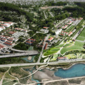
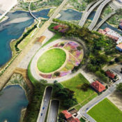
EPA Announces Winners of the 2013 Campus RainWorks Challenge
Standard urban development builds systems designed to move stormwater quickly away from where it falls. The efficiency of gutter and pipe systems allows stormwater to carry sediment, bacteria, nutrients, and even heavy metals into bodies of water. It also places more stress on natural waterways because runoff is quickly discharged into main systems, increasing peak flows. To encourage non-traditional thinking about drainage systems, the EPA has asked students to examine how green infrastructure can reduce these issues.

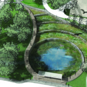
A seating nook designed beside a rain garden and wet meadow in a winning entry from Kansas State.
The EPA’s annual Campus RainWorks Challenge prompts university students to propose utilizing green infrastructure on their campuses. The competition aims to have students consider and promote both the functional and economic potential that green infrastructure can provide. It also strongly encourages interdisciplinary collaboration, being open to fields including landscape architecture, planning, engineering, biology, hydrology, and even economics. Each entry is judged on its effective performance, its innovation and value to campus, the level of interdisciplinary collaboration, and level of proper documentation. This April, the EPA announced winners from 84 team entries in two categories, Master Plan and Site Design.
Master Plan Category | First Place: University of Florida
The University of Florida nabbed first place in the Master Plan category. The team developed a proposal which treats the stormwater produced in a 67.6 acre watershed on campus for rainfall events up to a 100 year storm. At the University of Florida, stormwater is handled through a complex network of pipes which convey the water to the south end of campus, released into natural water bodies, and ends up in Lake Alice, the original detention pond for built for campus.
Related Story: Philly Grad Creates Free Cloud-Based Stormwater Modeling Tool
The team proposed daylighting the underground stormwater infrastructure in an “artful treatment matrix”. In place of rapid conveyance systems, the team used surface-based green infrastructure to treat and slow the stormwater as preemptive pollution and flood mitigation as it moves from north to south on campus towards Lake Alice. The three-phased plan included a large bioretention pond to replace the current holding pit. Other measures include two more detention areas – one pond and a linear basin along a main thoroughfare – as well as rain gardens interspersed with playful water elements like a purple weeping pipe.
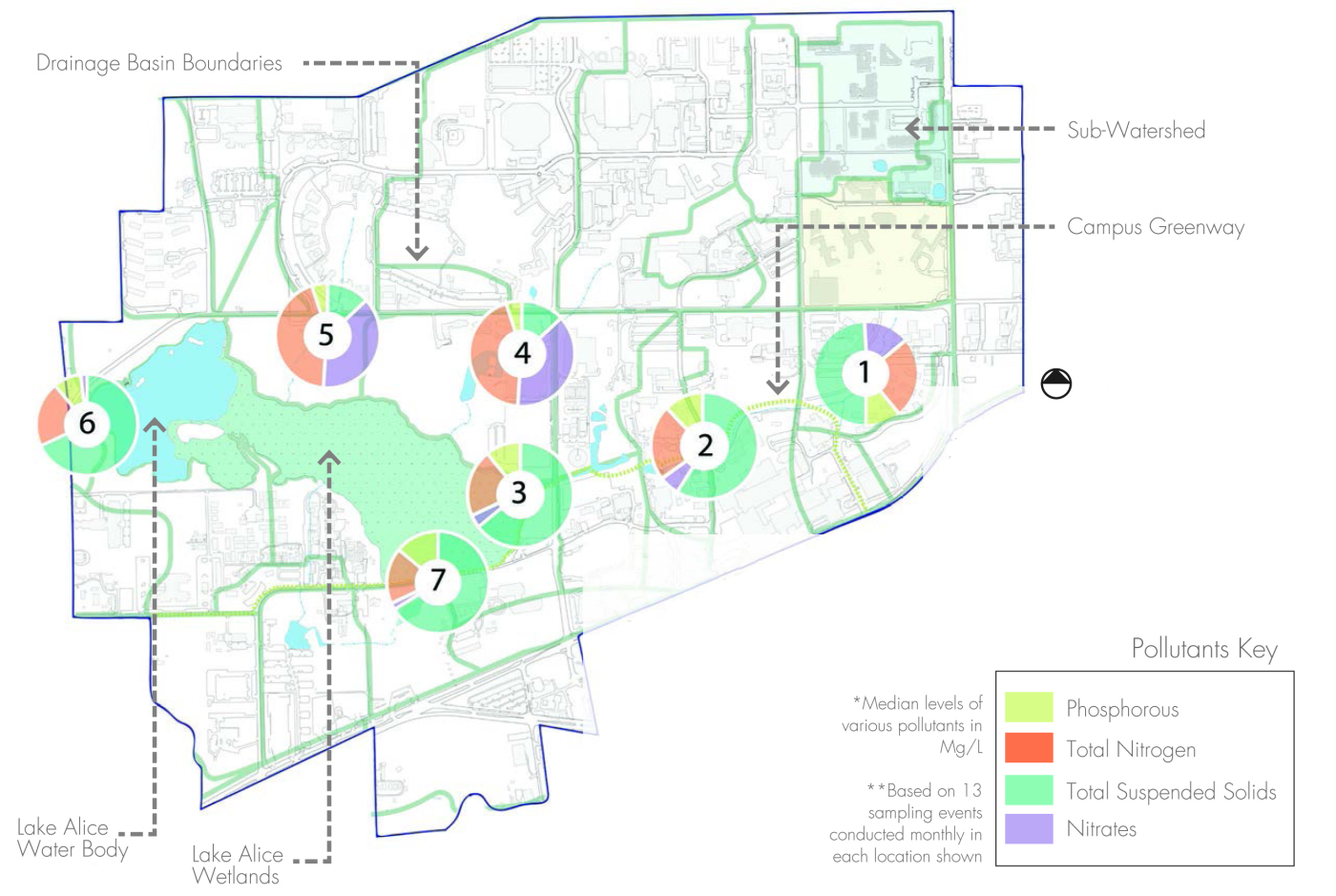
University of Florida: The map shows the focus watershed and downstream areas with significant pollution.

The plan of the Master Plan’s upper zone releases water from current infrastructure into the proposed above-ground system. The final stage of the campus stormwater detention system is shown in the lead image.

A purple pipe, which later discharges into green infrastructure, calls attention to the path of stormwater throughout campus.

Bioswales separate vehicular and pedestrian circulation. They add both functional and aesthetic value to the street.

The Yulee Pit is the final point in the proposed campus water retention and mitigation system.
Site Design Category | First Place: Kansas State University
In the Site Design category, Kansas State placed first. The team responded to a $5.1 million recommendation from a consulting engineer firm to fix campus stormwater issues by enlarging the existing pipe network. The team wanted to demonstrate that the issues could be addressed through green infrastructure methods by slowing and reducing the stormwater entering the system. They focused their proposal on a strip of lawn bordering the commons next to the campus library.
Related Story: 5 Resiliency Lessons from NYC Stormwater Projects
As a highly visible part of campus, the design provides both technical performance and education. Two small, existing depressions were reworked to create a wet meadow. Combined with several small rain gardens, the site retains all the stormwater from a one year storm and 65% from a ten year storm. The team also utilized a striking combination of details to bring attention to the functional stormwater management features. Where the site borders the commons, stone runnels collect water, which is then conveyed under decorative grates across the path into the bio-retention areas. The vegetation scheme reflects a native Kansas prairie ecosystem, transitioning from wet to mesic to dry plant communities as the terrain moves above the retention zone. The native vegetation, in addition to its stormwater benefits, replaced low-functioning irrigated lawn.

Kansas State: The proposed site creates a new, more lively front for the university library facade.

While the existing site condition sends all runoff off site in pipes, the proposed design retains all the runoff produced in its watershed from a one year storm event.

Stormwater runoff is collected from the lawn and conveyed across the path to bioretention areas.

The plant palette developed by the Kansas State team reflects a sensitivity to native plant communities and topography.
To see the winning entries, as well as second place and honorable mentions, go to the EPA’s Campus RainWorks Challenge page. The 2014 call for entries has already begun. Registration closes October 3, and entries are due December 19.
All images provided by the EPA.
- 1
- 2