
When you start your 3D model, you start with a cad base, just like you have for your plan graphics and for your Bid Set. However, there are some tweaks that need to be made, and things you have to pay more attention to then normal. In this tutorial I’m going to take you up to the point of bringing your model into SketchUp. Next time we will get into tweaking topo and base modeling, and then after that, the fine modeling level, and adding plants. But for now, we are focusing on the base, as without a good base, the modeling process will be much more difficult and time consuming.
Note: When you use CAD, use Polyline, for the love of god. It is only in EXTREMELY rare cases that line works BETTER than poly line, and this is NOT one of them.
Step 1: Clean up your normal CAD base
To start, open your normal CAD base and save a copy of it in a new folder. Once you have your copied CAD file, there are a few fairly simple things you can do to clean up your base. The first is to carefully go through and create new layers based on the different materials you will have in your model, and you should name them based on what material they will be to reduce confusion.
A key point here is to make sure you have a unique layer for each of your materials, as the layers will carry over to SketchUp. Once you put everything on the correct layer, make sure all your corners are square and your polys close. You are going to have to close them eventually anyway to make them into surfaces in SketchUp, so you might as well do that now in the friendly confines of CAD.
Step 2: Topography- think like a computer, one triangle at a time
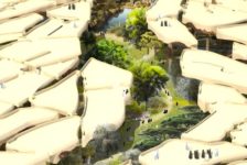
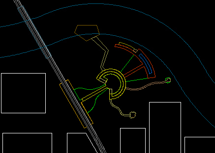
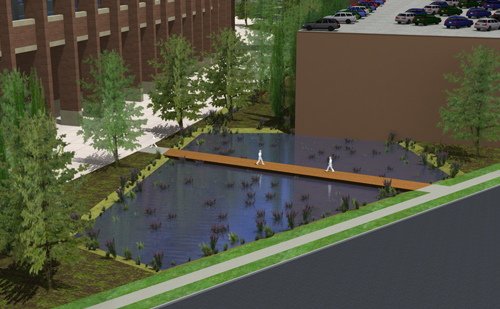
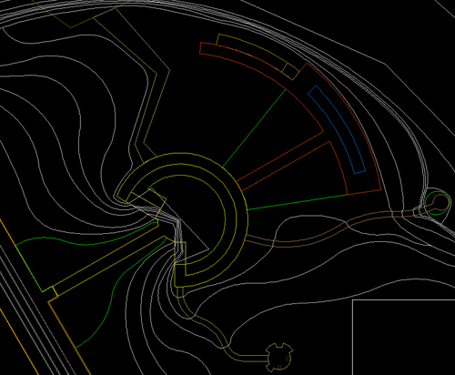
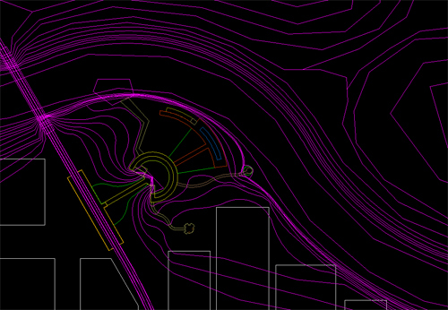
Now its time to add topography. There are two main issues you are going to have to address with topo: thinking about how the computer will create the surface, and thinking about making what goes on those surfaces. This is the basic topo for the fictional park design I am working with.
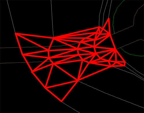
The first thing to realize is how SketchUp (or any other program) will create your topography. As a quick intro/refresher- all 3d models are comprised of polygons- more precisely, triangles. That is because 3 points makes a plane, and computers, as amazing as they are, cannot make true curves. They can make thousands of tiny angles, but not an actual curve (there are ways to fake it more, but its still really a post production fake). That is why when you make a curve in CAD and then zoom in it is suddenly angled lines that are kind of in the wrong spot. Getting back to the point- your computer will make the smooth, rolling landscape by making a bunch of triangles and “softening” the edges, but it is still made up of triangles. These triangles are made by drawing lines from intersections on one line to intersections on another line. For example, with these lines:
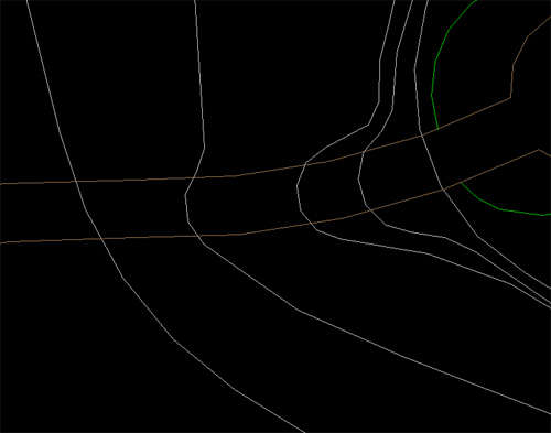
This is (hopefully) where the triangles would be made:
This means 2 main things for your drawing. First, and easiest: the further the camera is, the less detail that you will see, so by simplifying the lines that the triangles are made from, you reduce the number of triangles, and decrease rendering times. So, when you are getting to areas that are far out of your model, and don’t need a lot of detail because they will act simply as context, you can often get away with making those smooth curves into sharp angles, and get nearly the same result for far less CPU power.
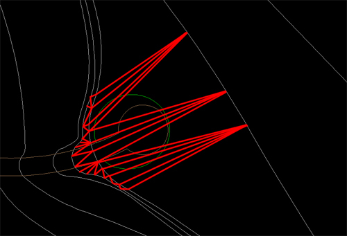
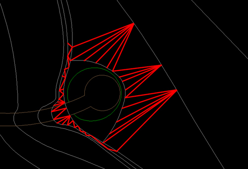
The second, and more tricky point: if you have a flat terrace, on your topography map that is shown by an area with a bigger spread in its contours, because we interpolate a steep slope suddenly being flat as essentially a level slope, even if the contours imply a 5% slope, because the slope is likely steep beyond the last “steep” contour. However, the computer only sees what you put in, and cannot interpolate unevenly spaced contours, so it will have a slope that is steep from one contour the next, and then makes a hard turn to a 5% slope, and then a steep drop again. Because of this, you have to edit your contour layer, and break one of the cardinal rules of topography- you are going to have a contour line split and then rejoin. to create a truly level area you are going to have to surround the entire level area with equal contour lines, forcing the computer to see the contour lines your mind is reading between the lines on the map.
Level area the way its drawn on a map:
![]()
The way that would be interpreted by a computer:
The “fix” by breaking the rules:
![]()
The new triangle map (level area skipped for clarity):
Step 3: What is that path going to look like exactly?
The last big complication to 3d modeling on topography is getting your paths and areas that overlap topographic changes to look right on the slope. The problem is, again, the fact that the surface of the ground will be made of triangles. this becomes an issue because your triangles may not line up with the edges of materials. There are a few things you can do to address this. First, you could simplify your topography so that a minimal amount of it intersects site amenities, as I was able to do in my thesis project, as there are not many large grading changes other then wetlands.
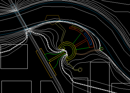
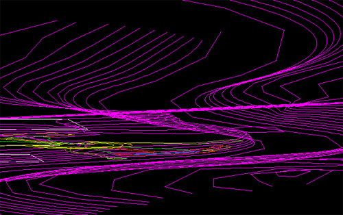
At times, however, that is not a viable option, and you need to be able to control what your slope looks like on a given face. To do that you need to ensure that a given section of slope is laterally level. The first step for that is to edit the contours so that the slope crosses the area in a straight line perpendicular to the slope. This is what my topography looks like after I add my loops for level ground:
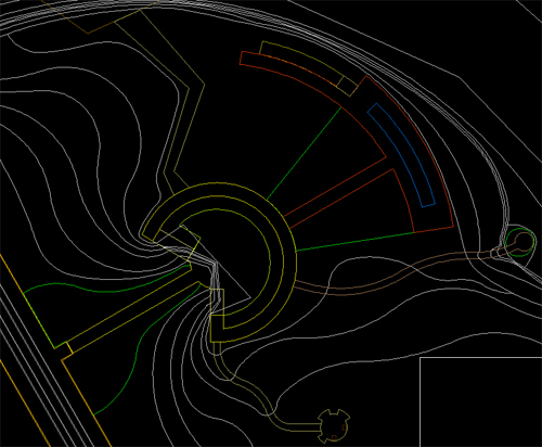
You want to change all of the sloping areas here:
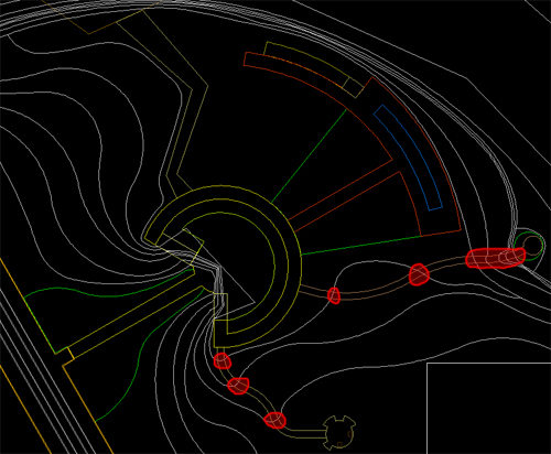
To look like this:
Once you do this, you wait for further fixing until you are in SketchUp, and that will come next week…
Step 4: Elevate to a New Level
The next thing you have to do is elevate your topography and items to the levels they will be at. In AutoCAD, you want to open the properties window for each contour line individually. Once there, you will see an option for “elevation”. This is where you input the height of a given contour line. Go through each contour line, and object and assign them to the appropriate elevation. I personally like to also change them to a set color, like magenta, so I know what I have moved. Then once everything is adjusted you can select all and move the color back to “by layer”.
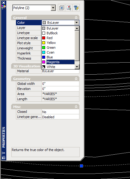
Once you have everything moved to the correct elevation, you can change the color back, and finish the fix for uneven paths.
Now its time to import into SketchUp and let the real fun begin…