


An AutoCAD tutorial on How to Create the Perfect Flow in Your Drawings from our resident AutoCAD expert UrbanLISP. Whether you are designing a path for a small garden or developing a master plan, chances are strong that you will draw a few lines that are curved. Creating these curves can be fairly easy, but there is more behind it than you might initially think. It’s good to know what to pay attention to, because it also easily can go wrong. And then things can get really awkward — if not disastrous. To prevent these situations, we are going to have a look at the science behind the curve. Before we talk about flows, we are going to have a quick look at two straight lines. When one straight line approaches another, both lines make an angle with each other. When this angle is exactly 90 degrees, it’s perpendicular. When they make an angle of 180 degrees, they actually don’t make an angle. In that case, they are parallel.

Creating seamless curves at City Square Urban Park. Photo credits: See Chee Keong
How to Create the Perfect Flow in Your Drawings
(No time to read the full article, scroll down to the video)
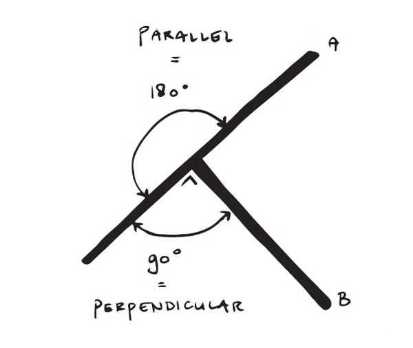
Image credit: UrbanLISP
Fillet
Now we understand perpendicular and parallel lines. Most CAD programs have a function to connect lines with a curve. In AutoCAD, this command is called fillet. When you use this command, you’ll create a perfect flow from one line to the other with an arc — a curve. The fillet command helps a bit by shortening or extending the lines we used for this flow. The arc it created is based on the geometry of these lines. The arc has a start, an end, and a center point. Let’s have a look at the position of those points. The fillet command extended or shortened the lines we selected based on the radius we defined. When we take the end point of each line that connects with the arc and draw a line perpendicular from it, those lines will cross each other at some point. And guess what — this is the center point of the arc that was created with fillet.

How would you go about making the curves in these walls? Baan San Ngam. Photo credit: Pirak Anurakyawachon
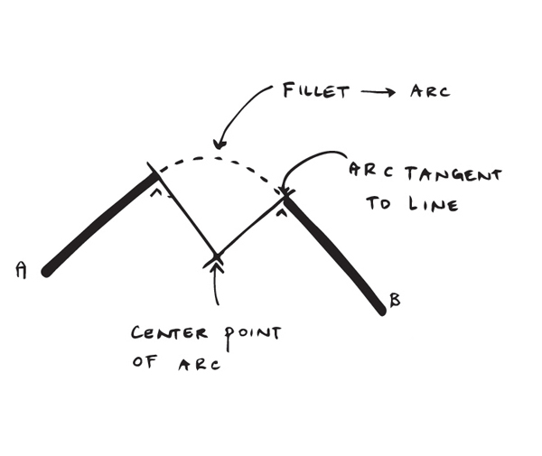
Image credit: UrbanLISP
What is Tangent?
If you have a hard time understanding tangency, try to imagine that you have a basketball and a plank. The basketball is on the ground, with the plank on top of it. You don’t have to balance the plank; one side can touch the ground. In essence, you’ve created a tangent flow. Imagine the plank is cut exactly on the point where it touches the basketball. It doesn’t matter how far the plank sticks out, the point where they connect will always be tangent.
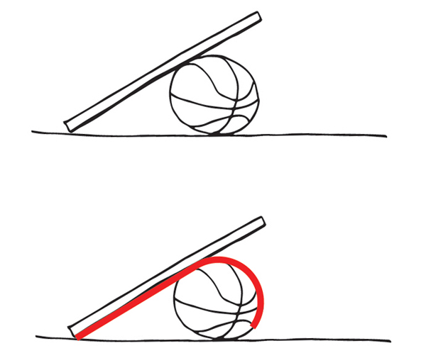
Image credit: UrbanLISP
The Circle Method
With fillet, AutoCAD takes a few actions out of our hands. You can essentially do the same thing with the circle command. When starting this command, there are a few options in the command line. One of them is TTR. It stands for Tan Tan Radius, which is short for Tangent Tangent Radius. When we use this option, the command will ask you to click a point on two different linear entities. It will use a special snapping mode called “deferred tangent” that will consider the point you’ve selected more like a search area than an exact point. After picking the points, you have to define a radius. The command will draw a full circle with a specified radius. The circle will be tangent to both linear entities you’ve clicked with the “deferred tangent” snapping mode. After that, it’s just a matter of trimming the circle and line, and you’ll have the same effect as fillet. There might be cases, however, when you don’t want the lines to be trimmed. In that case, this method is very helpful.
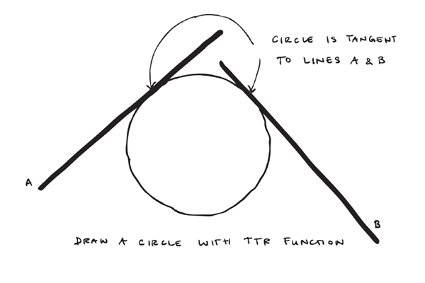
Image credit: UrbanLISP
Offset
When you work in a CAD program that doesn’t have a fillet command, the offset command could help you out. If you want to make an arc with a radius of 25 units, you can make an offset of the linear entities of 25 units and find the intersection point of those entities. Use that intersection point as center point for the circle you want to draw, and you’ll see the circle will be tangent to both original linear entities.
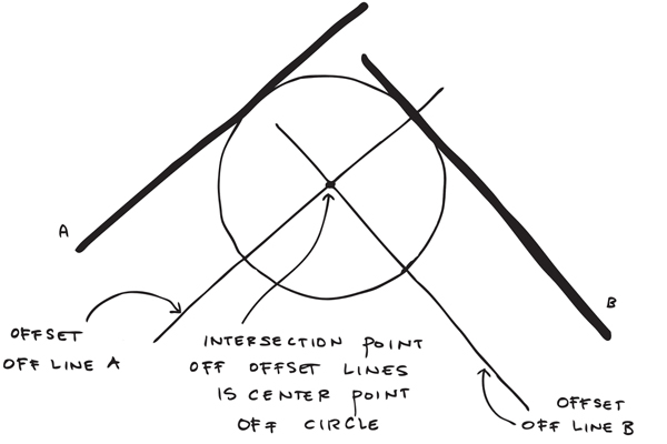
Image credit: UrbanLISP
The Other Way Around
Previous examples were with straight lines. Fortunately, fillet also works with arcs. It will extend or shorten them to fit a tangent arc. With three consecutive tangent arcs, there’s a real nice flow appearing.
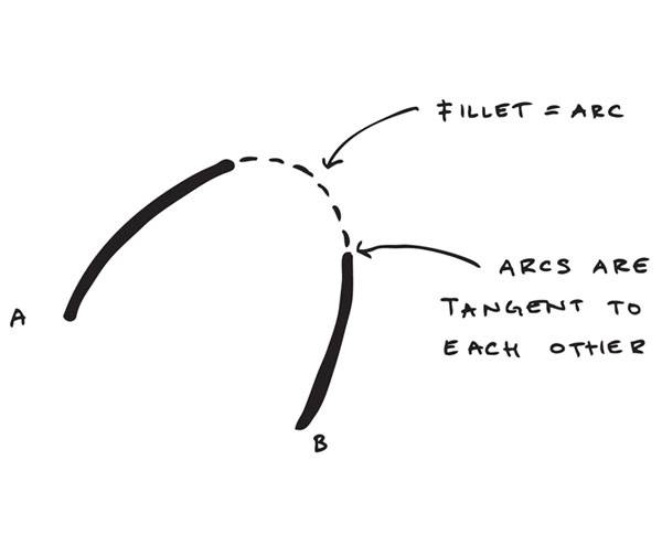
Image credit: UrbanLISP
- 4 AutoCAD Commands to Draw Paving Patterns on Curving Paths
- How to Show Topography in your Plan Drawing in AutoCAD
- How to Place Large Quantities of Trees in a Master Plan Instantly with AutoCAD
IN THESE EXAMPLES, we basically used fillet to create rounded corners between the entities we already had. But what if we already have those rounded corners and want to make the connections between them? If you want to create straight connections, you can use the line command. When picking the points, you can override the snap options to tangent snapping by typing “tan”.
Recommended Reading:
- Digital Drawing for Landscape Architecture by Bradley Cantrell
- Detail in Contemporary Landscape Architecture by Virginia McLeod
Do this for both points of the line and select a point somewhere on the circle. The line that will be drawn will be tangent to both circles. If you want to draw a rounded connection, you revert to the circle method and use the TTR feature.
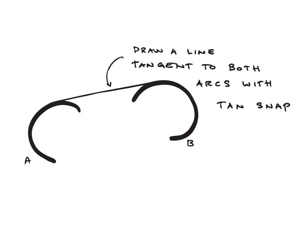
Image credit: UrbanLISP
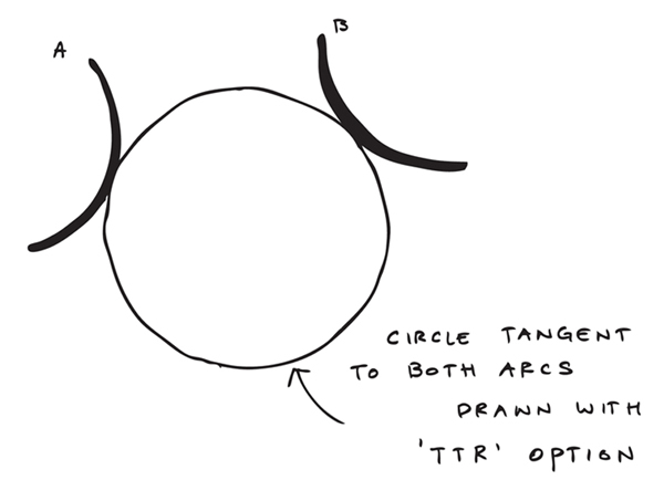
Image credit: UrbanLISP
Select a Single Entity
So fillet allows you to connect two linear entities with a curve. But what if you only have one entity? You’ll have one entity, so you know you want to be tangent to that one. But where to go? The UrbanLISP “Tangent Arc to Linear” command allows you to place a tangent arc as an extension of a linear entity. Where the arc goes is for you to decide. Start by selecting a linear entity. This can be any entity — a line, arc, or polyline, but even a spline or an ellipse. Select the entity on the side you want to place the arc; the command will take that side as base point. After that, it’s just a matter of aiming the arc and clicking in the drawing. You can do the same thing with the “Tangent Arced Segment”. If you use this command, you can select polylines. The arc you create will be added as a segment to the polyline.
Achieve Perfection
OK, we now know how to create a flow. But how do we make it perfect? If you are a student, you are probably only doing theoretical plans. Once you become a professional, you will develop plans toward realization. The more accurate your drawings are, the more serious engineers, constructors, and architects will be about applying it. If you draw a road with a radius of 24.78 units, it will not be welcomed with a lot of enthusiasm. Why not make the radius 25 units?

Curves at Cumberland Park. Photo credit: Hargreaves Associates

Maybe one day you’ll be planning curves like these ones at Zhangjiagang Town River Reconstruction. Image courtesy of Botao Landscape (Australia)
See the full tutorial on How to Create the Perfect Flow in Your Drawings:
–
Recommended Reading:
- Digital Drawing for Landscape Architecture by Bradley Cantrell
- Detail in Contemporary Landscape Architecture by Virginia McLeod
Article by Rob Koningen
You can see more of Rob’s work at UrbanLISP
Published in Blog